Serial Communication with the Host Computer
An Arduino microcontroller can send messages back to the host computer over the USB connection. The host computer can display these messages as text in the Serial Monitor or as a dynamic plot in the Serial Plotter.
The messages from the Arduino board are useful for indicating the state of a running program. For example, the messages could be measurement data from sensors connected to the Arduino board. The messages are also useful during debugging. Programmers typically insert temporary print messages to understand the what is happening when the sketch is not working according to plan.
For additional details and examples, see Serial Print in a Nutshell and the information in the following outline.
Table of contents
- Communication between the Arduino board and host
SerialObject- Using
Serial.printandSerial.println - Specifying precision of numerical values
- Using the Serial Plotter
- Waiting for the
Serialobject to start
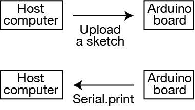
Communication between the Arduino board and host
When an Arduino board is connected to a host computer via a USB cable, the communication goes in both directions. Uploading a sketch to the board sends data (mostly) from the host to the board. Some handshaking between the host and board is required to make sure the data is communicated correctly, so there is communication in both directions. A running sketch executing Serial.print or Serial.println commands send most of the data from the Arduino board to the host.
Serial Object
The standard Arduino library provides a Serial object, which has three commonly used methods.
Serial.begin()
Serial.print()
Serial.println()
Consult the reference page at arduino.cc for a full list of methods for the Serial object.
Serial.begin is used only once in a sketch, typically in the setup function. Serial.begin only establishes the communication. It does not send a message.
Serial.print and Serial.println are used inside any function (setup, loop or user-defined) to send messages to the Serial Monitor or Serial Plotter.
Here is a simple sketch that demonstrates the use of Serial.begin, Serial.print and Serial.println.
void setup() {
  Serial.begin(9600);             //  Initialize the Serial object at 9600 baud
  delay(3000);                    //  Wait for the USB connection to be established
  Serial.println("Ready to go");  //  Send confirmation message to the Serial Monitor
}

void loop() {
  Serial.print("Time is ");       //  Begin the line of text output
  Serial.print(millis());         //  Add the current clock value to the output
  Serial.println(" ms");          //  End the output with text and a newline
  delay(1000);                    //  Slow down the output to the Serial Monitor
}
The argument of Serial.begin is the baud rate, basically the number of bits per second that the devices at each end of the serial connection send and are expected to receive. The Wikipedia page (among other sources) has more information on the defintion of baud rate. For most sketches a baud rate of 9600 is sufficient. You should make sure that the baud rate specified in the Serial.begin statment matches the baud rate in the Serial Monitor or Serial Plotter.
The arguments of Serial.print and Serial.println are either text or numeric values, as described in the following section.
Using Serial.print and Serial.println
Serial.print and Serial.println usually take one input argument that is either a string or a number. The exception to the one-input case is when a second input argument is used to specify the precision of a numerical value, as described below.
The difference between Serial.print and Serial.println is in what happens to the output in the Serial Monitor after the message is received. The argument of a Serial.print command is displayed on the Serial Monitor without advancing to the next line.
The argument of the Serial.println method causes the Serial Monitor to display the message and advance the display to the next line. Think of the ln at the end of println as meaning “print message and go the next line”. In contrast, the Serial.print method causes the Serial Monitor to display the message without advancing to the next line.
Consider the following code snippet
Serial.print("Hello");
Serial.print(" there");
Serial.print(" from");
Serial.println(" Arduino!");
Those statements would cause the following message to appear in the Serial Monitor.
Hello there from Arudino!
The text from the three Serial.print statements in the preceding example is appended without advancing to the next line. The final Serial.println(" Arduino!") appends the last word and advances to the next line.
Note that the last three statements include a space before the text argument. The spaces at the start of the Serial.print and Serial.println arguments provide the spaces between words when the entire message appears on the Serial Monitor.
Also note that the message in this example could (and should) be sent with a single, Serial.println(); command. However we are using the more inefficient code to demonstrate the difference in behavior of Serial.print and Serial.println.
Specifying precision of numerical values
When sending numerical values to the Serial Monitor, a second argument to Serial.print and Serial.println can be used to specify the format. This is most commonly used to change the number of digits are displayed to the right of the decimal point for floating point values. Consider the following code snippet. The complete sketch can be downloaded here.
void setup() {
  Serial.begin(9600);             //  Initialize the Serial object at 9600 baud
  delay(3000);                    //  Wait for the USB connection to be established

  float x = 17.954;               //  Assign arbitrary value to x
  float y = sqrt(x);              //  and store square root of x in y

  Serial.println("  x      x,1     y      y,5");   //  Print header

  Serial.print(x);                //  Print x with default precision
  Serial.print("   ");            //  Add horizontal space to separate values
  Serial.print(x,1);              //  Print x with one digit to the right of the decimal point
  Serial.print("   ");            //  Add horizontal space to separate values
  Serial.print(y);                //  Print y with default precision
  Serial.print("   ");            //  Add horizontal space to separate values
  Serial.print(y,5);              //  Print y with five digits to the right of the decimal point
}
The output from the sketch is
 x      x,1     y      y,5
17.95   18.0   4.24   4.23722
Note that the floating point values are rounded to the appropriate number of digits.
Using the Serial Plotter
The Serial Plotter is an alternative to the Serial Monitor for displaying numerical data. The data sent to the host via serial.print and serial.println commands needs to be only numeric i.e. with no text on each row of data.
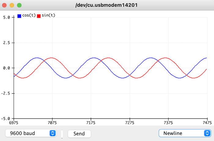
The following sketch demonstrates how to format data for the Serial Plotter by generating two columns of numbers and no extraneous text labels. The cosine and sine functions are used as convenient sources of data. You can download the sketch.
void setup() {
  Serial.begin(9600);                 //  Initialize the Serial object at 9600 baud
  delay(3000);                        //  Wait for the USB connection to be established
  Serial.println("cos(t)\tsin(t)");   //  Send header labels for the numeric data
}

void loop() {
  int dt;
  unsigned long t;
  float theta, tau, cost, sint;

  t = millis();               //  Current clock time in milliseconds
  tau = 1000.0;               //  Period of the cosine and sine waves
  dt = tau/150;               //  Delay in milliseconds between data points
  theta = 2*PI*t/tau;         //  Argument of cosine and sine in radians
  cost = cos(theta);          //  cosine of theta
  sint = sin(theta);          //  sine of theta

  Serial.print(cost);         //  Print value in first column of output
  Serial.print("\t");         //  Add a tab character between columns. Spaces also work.
  Serial.println(sint);       //  Print value in second column and a newline
  delay(dt);                  //  Wait for the next time
}
Before uploading the sketch, close the Serial Monitor if it is open. You cannot use both the Serial Monitor and Serial Plotter at the same time. The Arduino IDE may also give error messages when you first try to open the Serial Plotter window. If that happens, try opening the Serial Plotter window and uploading the sketch again.
Running the demo_serialplotter sketch produces a dynamic plot captured in the following screenshot.
Waiting for the Serial object to start
Depending on the host operating system and the Arduino board, there is usually a slight delay between the completion of the Serial.begin command and the time that the serial connection between the host and Arduino board is ready for communication. This delay is usually not important except when messages to the Serial Monitor are sent from within the setup function.
Consider the setup function from the sample code above
void setup() {
   Serial.begin(9600);             //  Initialize the Serial object at 9600 baud
   delay(3000);                    //  Wait for the USB connection to be established
   Serial.println("Ready to go");  //  Confirmation message
}
If the delay(3000) statment is removed, then for some combinations of host and Arduino board, the “Ready to go” message might not appear on the Serial Monitor. Without the delay(3000), the “Ready to go” message might be sent to the Serial object before the serial (USB) connection between the host and Arduino board is established. In that case, the “Ready to go” message is lost.
Instead of using the delay(3000) statement, Arduino programmers can use a while loop as follows
void setup() {
   Serial.begin(9600);             //  Initialize the Serial object at 9600 baud
   while( !Serial ) { delay(10); } //  Wait for the USB connection to be established
   Serial.println("Ready to go");  //  Confirmation message
}
The !Serial expression will be true until the Serial object is ready. In other words, the value returned by Serial will be equivalent to false (and !Serial will be true) until the Serial object returns a non-zero value. The amount of the delay (10 milliseconds in this example) in the body of the while loop does not matter as long as it is small.
The use of the while( !Serial ) { delay(10); } expression has the advantage of creating the shortest possible wait. As soon as !Serial is false the code can continue, which is usually shorter than the 3000 millisecond delay caused by delay(3000). Usually differences in short wait time at the start of the sketch doesn’t have a significant practical impact.
However, there is a big disadvantage of using the while( !Serial ) { delay(10); } expression if the Arduino board is going to be deployed untethered from the host. For example, if the board is disconnected from the host after the sketch is uploaded and the board is connected to a battery, the value of !Serial will never by true. This causes the sketch to stall and become useless.
As long as the sketch is always running while connected to the host, both the delay(3000) and while( !Serial ) { delay(10); } expression will work. In that case, the choice of technique to wait for the Serial object to start up is up to the programmer.
Finally, note that in many applications, the loss of the first few lines of output to the Serial Monitor is inconsequential, especially after the sketch is debugged.