Using a Micro OLED Display
Table of contents
- Overview
- Breadboard Connections
- Install the Adafruit SSD1306 Library
- Run the demo sketch from the Adafruit Library
- Run
OLEDdisplayFunctions.inoto display internal clock time - Run
OLEDambientLight.inoto display time and ambient Light Level
Overview
Small Organic Light-Emitting Diode (OLED) displays are relatively inexpensive devices for text and graphical output from an Arduino board. This web page demonstrates how to connect a 128 x 32 or 128 x 64 micro OLED display from Adafruit to the Adafruit Feather nRF52840 Sense. The dimensions refer to the number of pixels in the horizontal and vertical directions. The following image shows the front and back of the 128x64 (top) and 128x32 (bottom) displays.
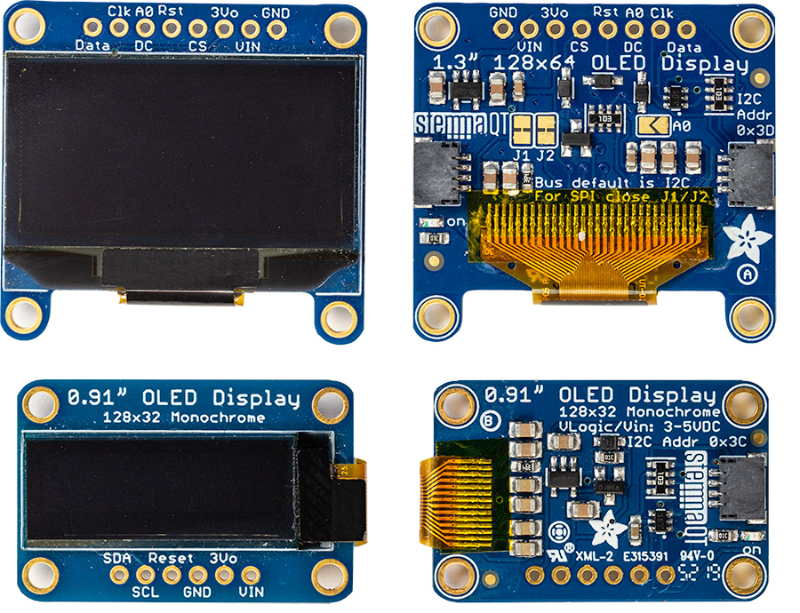
The display has a STEMMA QT (or SparkFun Qwiic) connector as well as solder pads for electrical connections. Because the Feather nRF52840 Sense does not have a STEMMA QT connector, we will use a breadboard and a connector cable with STEMMA QT on one end and breadboard compatible (male) pins on the other. These connectors are available from Adafruit, SparkFun, and Digikey.
The Feather boards distributed with the ME 120 kit has a Feather nRF52840 Sense with soldered headers. If your Feather board does not have soldered headers, you may want to watch the Adafruit tutorial on soldering headers.
Breadboard Connections
Insert the Feather nRF52840 Sense in the Breadboard
Align the header pins on the Feather board with the sockets on the breadboard. There should be one empty socket for each of the header pins. The header pins should all be straight, i.e. perpendicular to the board and aligned with the columns on the breadboard.
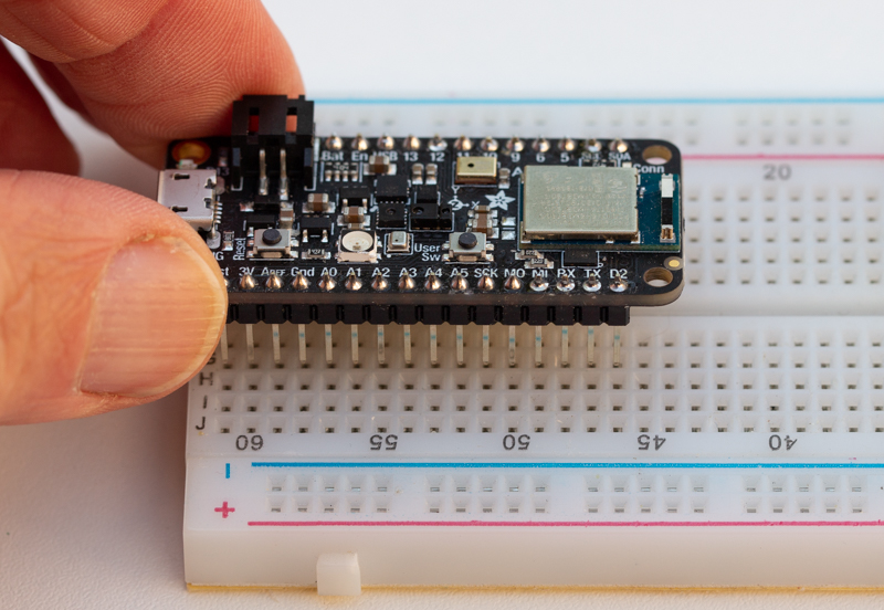
Make sure that when looking down on the Feather, there is at least one column of sockets that are not covered by the Feather. Because of the dimensions of the Feather and the breadboard, one side of the Feather will have one exposed column of sockets and the other side of the Feather will have two exposed columns of sockets. For this demonstration, it doesn’t matter which side of the Feather has two columns and which side has one column of exposed breadboard sockets.
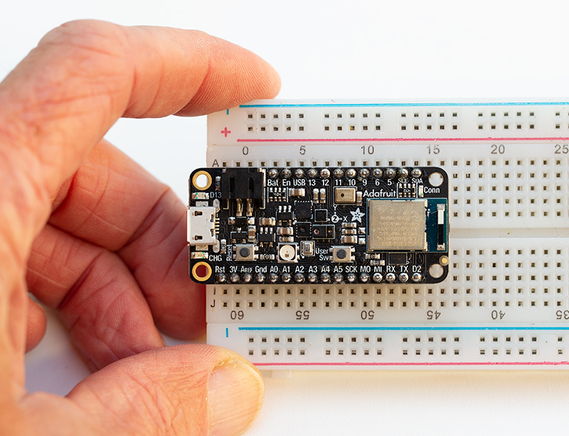
Press down on the Feather to insert the pins in the sockets. It may take some force to press the pins fully into the breadboard, especially if the breadboard is new. You an be firm as long as you keep the plane of the Feather parallel to the breadboard.
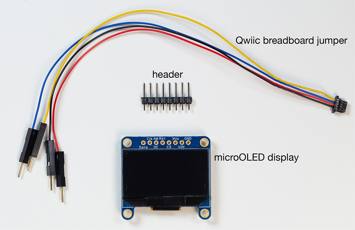
Adafruit OLED and STEMMA QT (Qwiic) connector
The kits for ME 120 include either an Adafruit 128 x 32 micro OLED display or a 128 x 64 micro OLED display along with a STEMMA QT (Qwiic) connector with male header cables. To use the OLED board with the Feather nRF52840 Sense, you will insert the STEMMA QT 4-pin plug into a socket on the OLED board. The exposed pins at the opposite end of the cables connect to the Feather on the breadboard.
Insert the STEMMA QT (Qwiic) Connector into the Micro OLED board
Be extremely careful:
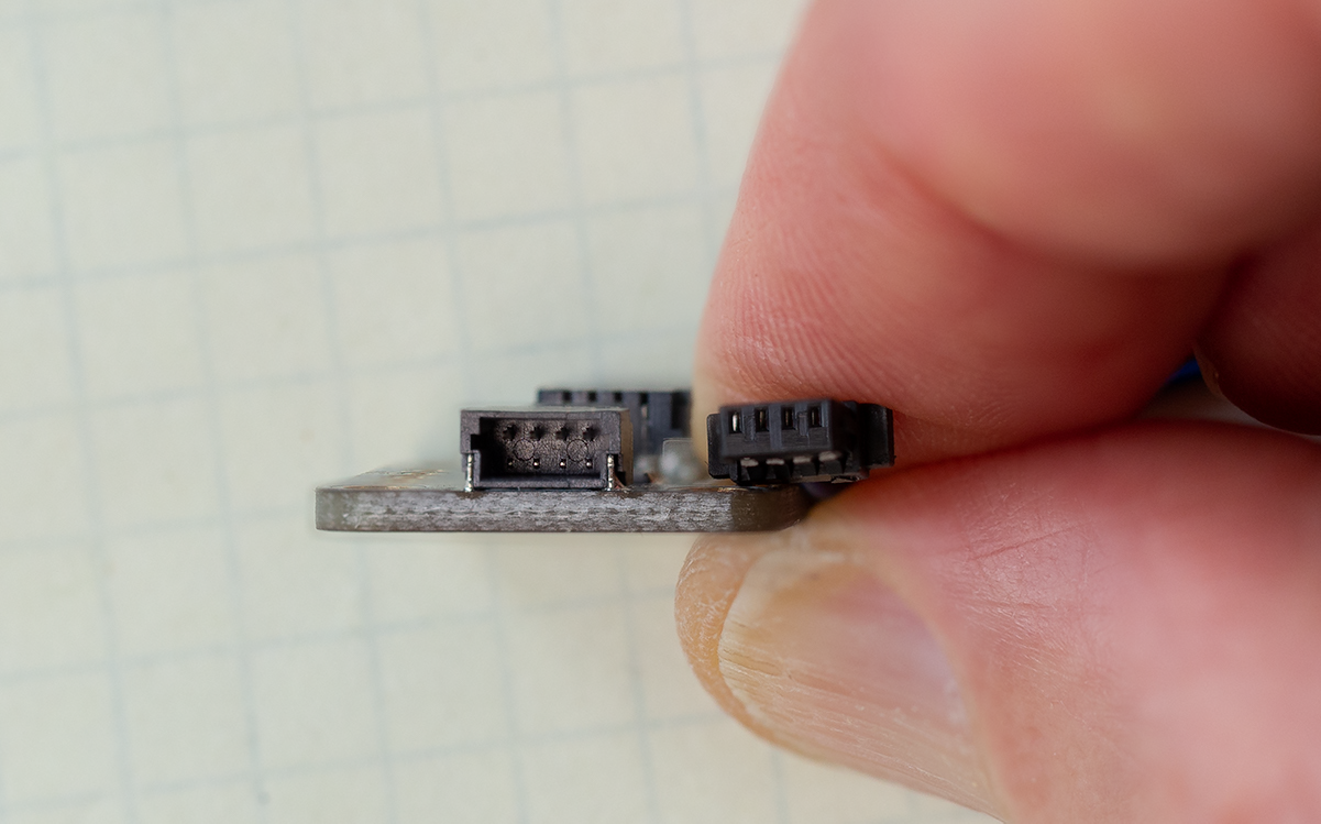
The STEMMA QT socket on the micro OLED board has four very small pins. If you insert the STEMMA QT cable incorrectly, you will crush the pins in the socket and the STEMMA QT connection will be permanently damaged. As with most projects involving electronics or small mechanical systems, excessive force is usually counterproductive. If there is resistance to pressing the plug into the socket, double check the orientation of the plug.
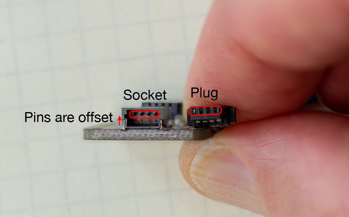
The following images show the STEMMA QT socket and plug. In the bottom image, the small pins in the socket and the corresponding holes in the plug are highlighted.
Carefully insert the plug end of the STEMMA QT cable into the corresponding socket
Connect the STEMMA QT connector to the Breadboard
The wires of the STEMMA QT connector have four colors, which correspond to the I2C communication protocol. Insert the male end of the STEMMA QT cable into the sockets adjacent to the pins on the Feather with the labels corresponding to the following color scheme.
Black:   GND
Red:     3V
Yellow:  SCL
Blue:    SDA
The SCL and SDA labels are for “clock” and “data”, respectively.
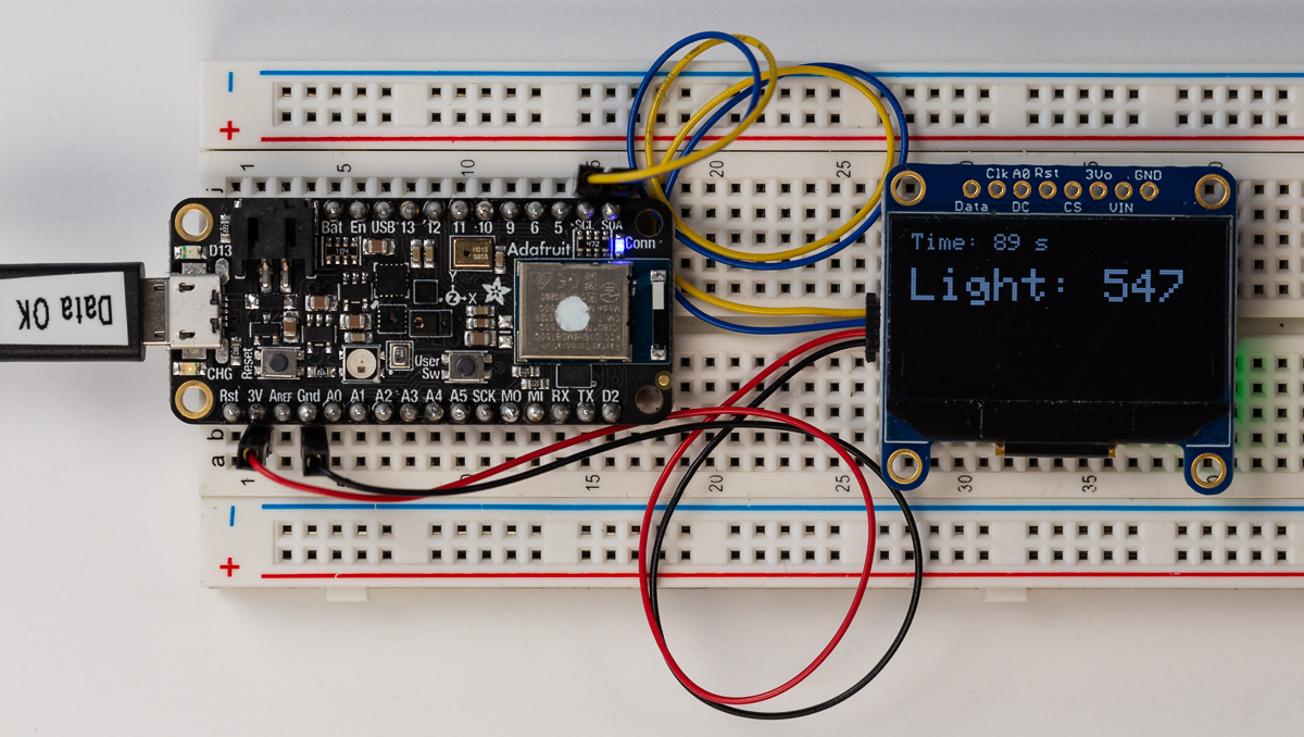
The following images shows the Feather nRF52840 Sense and the 128 x 64 micro OLED board on a breadboard. Header pins are soldered to the feather board, and those pins are inserted into the breadboard. The micro OLED board is resting on header pins that are not soldered to the board. The STEMMA QT cable is inserted into the socket of the micro OLED board, and the exposed pins on the opposite end of the STEMMA QT cable are inserted into the breadboard in sockets adjacent to the 3V, Gnd, SCL and SDA pins on the Feather.
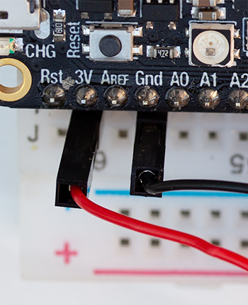
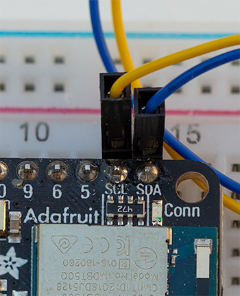
The following image shows a close-up of the 3V (power) and Gnd pins on the left and the SCL and SDA pins on the right
Install the Adafruit SSD1306 Library
To use the monochrome 128 x 64 or 128 x 32 micro OLED displays, you first need to install the Adafruit SSD1306 Library and the Adafruit GFX Library. The following steps with the Library Manager assume that you have properly configured the board support via the Arduino IDE Preferences.
From menu at the top of the Arduino IDE, select Sketch –> Include Library –> Manage Libraries…
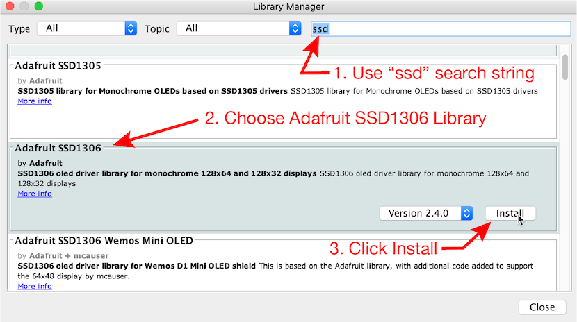
- Enter “ssd” in the search box to narrow the range of choices. Or, if you prefer, scroll through the entire list of libraries (not recommended).
- Choose the “Adafruit SSD1306” panel, which will cause the Install button to become visible.
- Click Install.
- The installer should ask if you want to install other dependent libraries, and you should check all the boxes of dependent libraries.
- After installing the SSD1306 library, check to see that the GFX library was also installed. If not, repeat steps 1 - 3 with these exceptions
- Search for “GFX”
- Install the “Adafruit GFX Library”
Run the demo sketch from the Adafruit Library
The Adafruit SSD1306 library includes example sketches to demonstrate features of the micro OLED display. The variants of the examples are appropriate for different types of connections and different size OLED displays.
It is important that you select the demo code that matches your display dimensions. Use the menus at the top of the Arduino IDE, select File –> Examples –> Adafruit SSD1306 –> Your display size demo. where Your display size demo is either
- ssd1306_128x64_i2c for the 128 x 64 OLED or
- ssd1306_128x32_i2c for the 128 x 32 OLED
Upload the appropriate sketch to the Feather board.
If you have connected the STEMMA QT cable to the correct pins on the breadboard, the demo sketch should display graphical and text images on the OLED board.
Run OLEDdisplayFunctions.ino to display internal clock time
The OLEDdisplayFunctions.ino displays the internal clock time in milliseconds and microseconds on the OLED display. The internal clock is restarted each time the microcontroller board is reset, or supplied with power after being disconnected from power.
Download the OLEDdisplayFunctions.ino sketch
Be sure to read the discussion below about the
OLED_I2C_ADDRandSCREEN_HEIGHTmacros. If these are not consistent with the OLED you are using, the OLED display will not show any response to the running sketch.
The purpose of OLEDdisplayFunctions is simply to show how to start the OLED display and dynamically update that display with new data. The internal clock time is just a convenient data source.
The Functions in OLEDdisplayFunctions refers to the use of C++ functions in the sketch to isolate the OLED-related tasks. The setupOLED function starts the connection between the external OLED panel and the running sketch. The updateOLED function accepts the time in milliseconds and seconds as inputs, and creates a display of those values on the OLED screen. The use of functions to compartmentalize tasks is strongly encouraged.
Run OLEDambientLight.ino to display time and ambient Light Level
The OLEDambientLight.ino sketch demonstrates how to display ambient light readings from the on-board APDS9960 sensor to the 128x64 or 128x32 OLED display. This sketch is much simpler than the Adafruit demo sketch (ssd1306_128x32_i2c) because it only uses the text display features of the OLED board. Although it is simpler, it demonstrates a practical example of how the OLED board can display sensor readings without needing to be connected to a host computer.
Download the OLEDambientLight.ino sketch and upload the sketch to the Feather. The following photograph shows the appearance of OLED display when the sketch is running. The time since the sketch started is shown in a small font at the top of the display. The current reading of the clear channel of ambient light levels is shown in a larger font.
WTF?
The sample codes have several statements like this
OLED.print(F("OLED is ready"));
What is the F( ) expression? Why does it appear in code related to the OLED display?
The first thing to notice is that the F( ) expression is only used with string constants, which are strings enclosed in quotes. The F( ) expression is not used with numeric variables.
The F( ) is a compiler macro that tells the compiler where a constant string expression is to be stored in the volatile memory available to the sketch. An expression inside the F( ) macro is stored in PROGMEM, the memory used for the instructions that the microcontroller executes. PROGMEM is distinct from SRAM (static RAM or random access memory) that is used for storing data. In short, using F( ) reserves more memory (SRAM) for data, at the expense of using some of the memory reserved for the program code itself.
Use of the F( ) construct is optional. For example, the expression
OLED.print("OLED is ready");
would also work. For simple sketches, and for newer microcontrollers with more memory, there may not be a practical benefit.
Just treat the F( ) construct as a recommended way of writing fixed strings to the OLED display. By “fixed” strings we mean a string that does not change while the sketch is running.
Summary Recommendations for Constant Strings
- As general practice, use the
F( )macro to increase the memory available to store data. The importance of this memory usage varies with the sketch and, obviously, how much data is being used. For many sketches, this is not an issue. - Do not use
F( )around numerical variables. The benefit ofF( )comes from moving strings that do not change into PROGMEM, thereby preserving SRAM. - The Feather nRF52840 Sense has a lot of memory, so the
F( )macro is usually not critical for codes on the Feather Sense. However, if you move your code to another Arduino board that has less SRAM, you may experience bugs that are very hard to understand and fix.
References
- https://arduino.stackexchange.com/questions/19330/store-string-using-f-macro
- http://www.nongnu.org/avr-libc/user-manual/pgmspace.html
- https://www.baldengineer.com/arduino-f-macro.html
- https://forum.arduino.cc/index.php?topic=91314.0