Analog Reading of a Potentiometer
Table of contents
- Overview
- Circuit diagram and analysis
- Breadboard connection
- Reading the voltage of the potentiometer wiper.
Overview
A potentiometer is a convenient source of voltage input to an Arduino board. In a practical sketch, a potentiometer provides a dial that a user can adjust to change the behavior of the sketch. For example, the voltage signal from a potentiometer can be used to set a motor speed, a temperature level, a sound volume, a light brightness or some other control parameter.
Circuit diagram and analysis
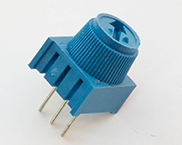
A potentiometer is a three-pin device that acts as an adjustable voltage divider. The photo on the left (below) shows a typical potentiometer with pins spaced for use in a breadboard.
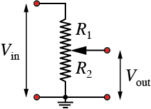
The diagram on the right (above) represents the circuit of a potentiometer. An input voltage is applied to the outer pins of the potentiometer, which results in a current flow (from Ohm’s law), of
The movable wiper sets the resistance , which determines the output voltage, .
Combining the preceding equations to eliminate gives
Breadboard connection
The potentiometer connections are summarized in the following table using the symbols that appear on the Feather board. Note that any of the analog input pins, A0, A1, … A5 would work for the analog reading of the potentiometer.
3V   One end of potentiometer
Gnd  Opposite end of potentiometer from 3V
A0   Wiper of the potentiometer
The 3V connection supplies power. Since the overal resistance of the potentiometers used as input devices are typically 10k or 20k, the current draw from the 3V supply will be minuscule.
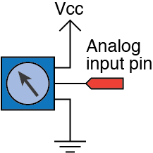
The following image is another representation of a potentiometer. Vcc is the supply voltage – 3.3 V in our case – and the analog input pin can be any one of A0, A1, … A5.
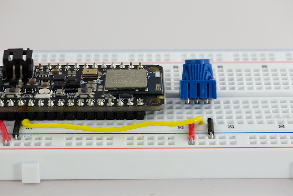
The following images show the breadboard from the top and side view for one version of the breadboard wiring. The power and ground pins of the Feather are connected to the power rails on the side of the breadboard. For this simple circuit, direct jumper connections would also work.
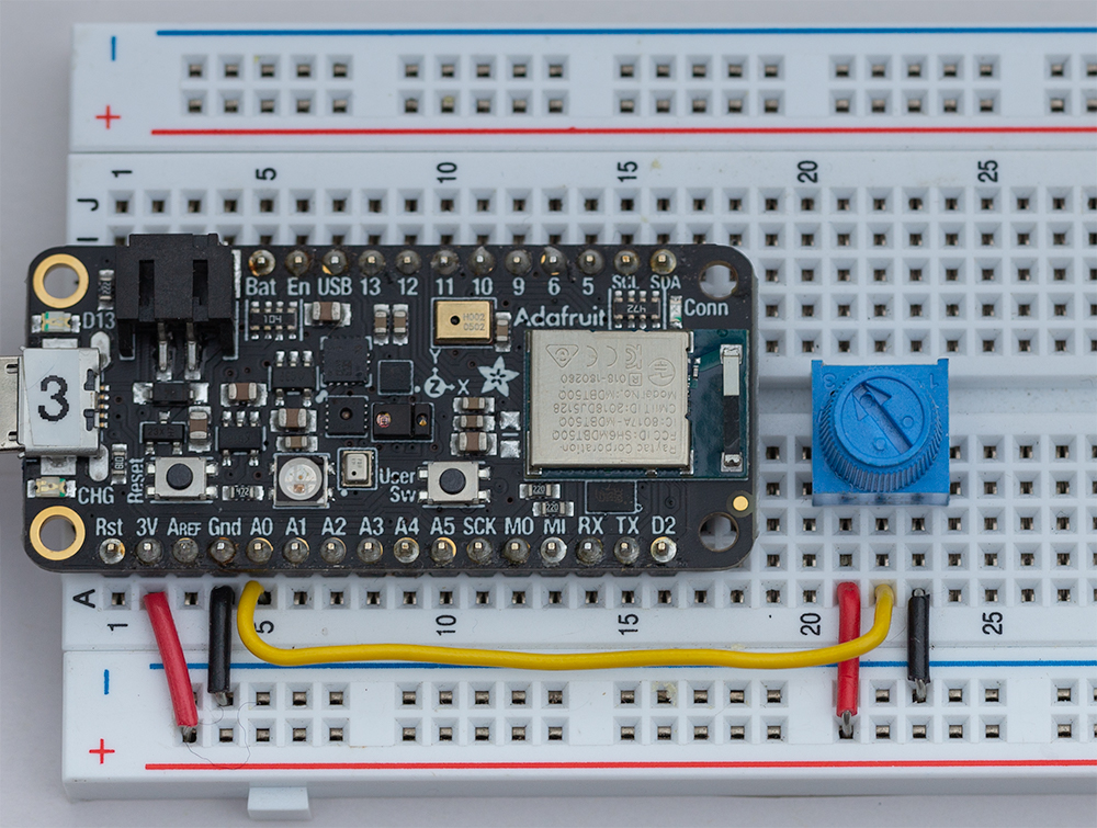
In the side view image, the potentiometer is partially removed to show how the three pins of the pot are matched to the red (3V), yellow (A0) and black (Gnd) wires.
Reading the voltage of the potentiometer wiper.
The readPotentiometer.ino sketch demonstrates the how to read a potentiometer using the default, 10-bit analog-to-digital (ADC) conversion on pin A0.
Download readPotentiometer.ino
//  File: readPotentiometer.ino
//
//  Read a potentiometer connected to an analog input pin of a
//  Feather nRF52840 Sense.  Use the default 10-bit analog input
//  resolution.

void setup() {
  Serial.begin(115200);
  while (!Serial)  delay(10);    //  Wait for USB connection
}

void loop() {

  int   potPin=A0, reading;
  float voltage;

  reading = analogRead(potPin);              //  Get 10-bit ADC reading
  voltage = (3.6/1023.0)*(float)reading;     //  Scale 10-bit value to voltage

  Serial.print(reading);
  Serial.print("  ");
  Serial.println(voltage);
}