Connecting the Feather nRF52840 Sense to External Devices
Table of contents
Overview
For some projects components in addition the on-board sensors and buttons will be needed. The following image identifies digital and analog input/output (I/O) pins that are used to communicate with external devices.
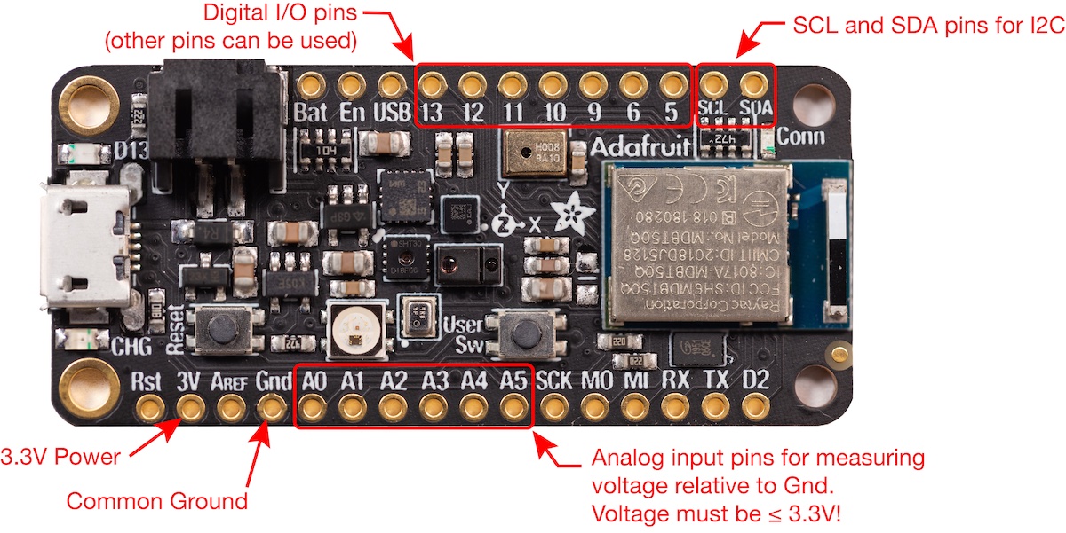
A “pin” in this context is one of the available electrical connections to the microcontroller. In the preceding image, pins appear as circular holes on the edges of the Feather board. The holes have a conductive plating that appears gold in color. Those holes can be soldered to headers that match the spacing of a breadboard. The holes can also be connected with probe clips or soldered to wires.
Analog Inputs
Analog input refers to measurement of voltages in the range 0 to 3.3V on the pins A0, A1,…,A5 in the image at the top of this page. More details are on this page
A potentiometer is a common source of an analog input signal. A potentiometer is a device that allows variable voltage to be selected from a given input range. Potentiometers are controlled by a knob or a slider, and are a simple way of providing user input, e.g. by selecting from a range of values, or by fine-tuning a circuit by adjusting a strategically located (and variable) resistor.
Digital Output
- Turn an external LED on and off
- PWM control
Motors
- Micro Servo motor
- DC motor drivers