Read the LSM6DS33 Accelerometer
Table of contents
- Overview
- Install the Accelerometer Library
- Upload the demoAccelFeathernRF52.ino sketch to the Feather nRF52840 Sense
- Viewing the Accelerometer Data
- Walk Through the Code
- Averaging to Smooth Acceleration Signals
- Further Reading
Overview
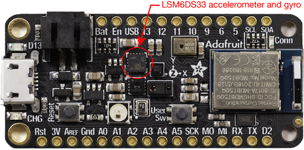
The LSM6DS33 is a sophisticated motion sensor that measures three degrees of acceleration and three degrees of gyroscopic motion (rotation about 3 axes). The chip has sensor hardware and on-board logic to detect motion events such as free-fall, tap and double-tap sensing. In addition the chip can detect tilt and provide pedometer data. The LSM6DS33 also exposes data from an internal temperature sensor that is used to reduce temperature sensitivity of the motion measurements.
The LSM6DS33 chip can communicate over I2C or SPI digital interfaces. Reading and processing the analog sensor data on an Arduino board is not necessary. Using the LSM6DS33 on the Feather nRF52840 Sense only requires writing code because the LSM6DS33 is mounted directly on the Feather nRF52840 Sense board.
This web page provides instructions on configuring the Arduino IDE for use with the on-board LSM6DS33, and a sample program for obtaining the accelerometer data from that chip. Since the code uses I2C communications, it should also work with an external LSM6DS33 connected to an Arduino board via I2C. In other words, the code is independent of the physical wiring as long as the I2C connections are correct. The full capabilities of the LSM6DS33 are described in the datasheet from the manufacturer, STMicroelectronics.
Adafruit provides extensive instructions for using the LSMDS33 and a software library with examples available on github. LSM6DS33 usage is also demonstrated in the sample code provided by Adafruit for the Feather nRF52840 Sense.
Install the Accelerometer Library
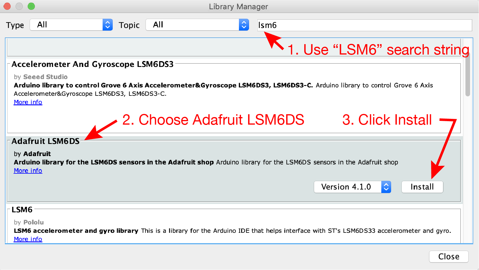
To write Arduino sketches that use the LSM6DS33, you first need to install the Adafruit LSM6DS Library. The following steps with the Library Manager assume that you have properly configured the board support page.
From menu at the top of the Arduino IDE, select Sketch –> Include Library –> Manage Libraries…
- Enter “LSM6” in the search box to narrow the range of choices. Or, if you prefer, scroll through the entire list of libraries
- Choose the “Adafruit LSM6DS” panel
- Click Install
Upload the demoAccelFeathernRF52.ino sketch to the Feather nRF52840 Sense
The demoAccelFeathernRF52.ino sketch demonstrates the accelerometer features of the LSM6DS33.
Download demoAccelFeathernRF52.ino and upload it to your board. While uploading the NeoPixel on the Feather nRF52840 glows green and then red. After the upload is complete you can open the Serial Monitor to see the accelerometer data from the sensor. Make sure the baud rate of the Serial Monitor is 11520, to be compatible with he code in demoAccelFeathernRF52.ino.
//  File:  demoAccellFeathernRF52.ino
//
//  Demonstrate use of accelerometer data on an Adafruit Feather nRF52840 Sense
//  Read the accelerometer, gyro and internal temperature data.  Print the
//  accelerometer data to the Serial object so that it can be displayed as
//  text in the Serial Monitor or as a continuous plot in the Serial Plotter
//
//  Adapted from feather_sense_sensor_demo.ino from Adafruit

#include <Adafruit_LSM6DS33.h>    // Library for support of LSM6DS33 chip
Adafruit_LSM6DS33 accelerometer;  // Create an accelerometer object

// --------------------------------------------------------------------------------
void setup()
{
  Serial.begin(115200);
  accelerometer.begin_I2C();        //  Start the I2C interface to the sensors
}

// --------------------------------------------------------------------------------
void loop()
{
  float ax, ay, az;
  sensors_event_t accel, gyro, temp;

  accelerometer.getEvent(&accel, &gyro, &temp);  //  get the data

  ax = accel.acceleration.x;   //  Copy to convenient variables. Not necessary
  ay = accel.acceleration.y;
  az = accel.acceleration.z;

  Serial.print(ax);                          //  Print plain data so that
  Serial.print("  ");   Serial.print(ay);    //  Serial Plotter can be used
  Serial.print("  ");   Serial.println(az);

  delay(25);                   //  Arbitrary delay to slow down display
}
Viewing the Accelerometer Data
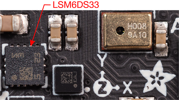
When connected to your computer the demoAccellFeathernRF51.ino sketch should produce a stream of three acceleration values in the x, y and z-directions. The orientation of the axes is indicated by the stencil on the board as shown in the following close-up view of the LSM6DS33 chip on the Feather nRF52840 that shows a stencil
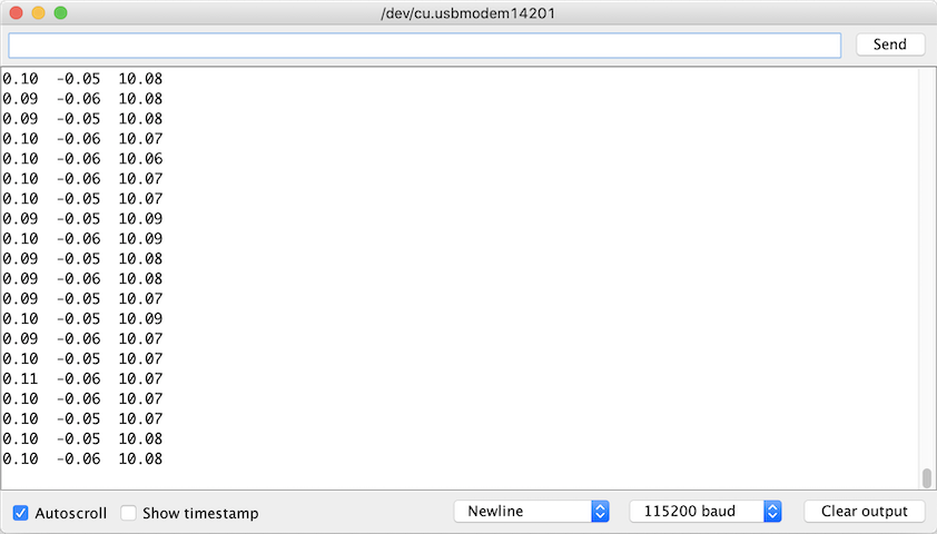
Numerical data in the Serial Monitor
The following image of the Serial Monitor shows the acceration data stream when the nRF52840 is resting upright on a desk. The columns, left to right are the , and components of acceleration in units of . Since the board was stationary when the readings were made, the only component of acceleration that is active is the acceleration of gravity, which is . The error in the component data show below is less than 3 percent.
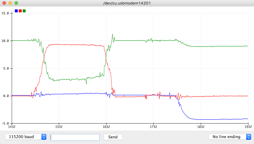
Graphical view with the Serial Plotter
Opening the Serial Plotter instead of the Serial Monitor (both cannot be open at the same time) produces an image like that below. The small color legend in the upper left corner associates blue, red and green curves with the , and components of acceleration. For the data shown below, the accelerometer was gently rotated about the and axes, which caused the magnitudes of the , and components of acceleration to shift.
Walk Through the Code
The demoAccellFeathernRF52.ino code performs these main steps:
- Include the
Adafruit_LSM6DS33.hlibrary - Create an
Adafruit_LSM6DS33object. In this code the object is calledaccelerometer - Start the accelerometer object
- Repeat the
loopfunction:- Read the accelerometer data
- Copy data from the accelerator object to local floating point variables
- Print the accelerometer data
We’ll examine each step in more detail.
Include the LSM6DS33 Library
The first step is to include the Adafruit_LSM6DS33.h library, which provides support for a wide range of features of the LSM6DS33 chip. You can read the code from the github repository.
#include <Adafruit_LSM6DS33.h>
The demoAccellFeathernRF52.ino code uses only the accelerometer features of the LSM6DS33 chip.
Create an LSM6DS33 Object
The next step is create or instantiate a LSM6DS33 object, which is the mechanism to communicate with the LSM6DS33 chip in the Arduino software environment.
Adafruit_LSM6DS33 accelerometer;
In this example the LSM6DS33 object is called accelerometer. An object is like a variable with properties for storing and retrieving data. You can use any valid variable name for the object name. The Adafruit_LSM6DS33 accelerometer statement invokes the constructor for Adafruit_LSM6DS33 objects. In this case the constructor does not require any input parameters. Therefore, accelerometer appears without any parenthesis.
Start the LSM6DS33 Object
The LSM6DS33 chip has internal hardware for converting raw accelerometer readings to digital values. Those digital values are communicated via I2C protocol from the LSM6DS33 to the nRF52840. You can learn more about the I2C from Wikipedia, Adafruit, Sparkfun and elsewhere. The Sparkfun resource is probably the most accessible if you are new to I2C and digital communication.
In the start() function, the single line
accelerometer.begin_I2C();
uses the .begin_I2C() method to create a new I2C connection between the nRF52840 and the LSM6DS33.
Retrieve and Print Acceleration Values
In the loop() function, values from the LSM6DS33 chip are retrieved and stored in sensors_event_t structs, the acceleration values are copied from the accel struct to simple floating point values, and those values printed with a standard Serial object.
First, variables in the loop function are declared
  float ax, ay, az;
  sensors_event_t accel, gyro, temp;
ax, ay and az are standard floating point variables that store the latest acceleration values from the LSM6DS33. The accel, gyro and temp are variables are declared as a sensors_even_t type which is defined in Adafruit_Sensor.h in the Adafruit_Sensor library. The sensors_event_t type is a struct, which is a C data type that can hold a collection of different variables. The sensors_event_t struct appears throughout the Adafruit libraries that support sensors with digital interfaces.
The following block of code retrieves accelerometer, gyroscope and temperature data from the LSM6DS33
accelerometer.getEvent(&accel, &gyro, &temp);
The call to the .getEvent() method passes pointers to the accel, gyro and temp structs. The &accel pointer is the address of the accel variable in memory. Pointers can be confusing, but they are a necessary feature of the C language. The important idea in this code snippet is that passing &accel to the .getEvent() method allows the .getEvent() method to change the contents of the accel struct.
The &gyro and &temp pointers are also passed the the getEvent() method because getEvent() requires three inputs, all of which must be pointers to sensors_event_t type. Values in gyro and temp that are returned by getEvent() are not used in the demoAccellFeathernRF52.ino sketch.
After getEvent() updates the contents of accel struct, the following statements copy the three components of the acceleration readings to the float variables, ax, ay and az.
  ax = accel.acceleration.x;
  ay = accel.acceleration.y;
  az = accel.acceleration.z;
With the accelerometer readings stored in ax, ay and az it is straightforward to send those values back to the host computer with the Serial object.
  Serial.print(ax);
  Serial.print("  ");   Serial.print(ay);
  Serial.print("  ");   Serial.println(az);

  delay(25);
After printing, a short, 25 millisecond, delay is used to slow down the pace of readings. That delay is not necessary.
Averaging to Smooth Acceleration Signals
Accelerometer readings can fluctuate rapidly due to vibrations of the object to which the sensor is attached. Sometimes those rapid fluctuations are important, e.g. when you are trying to measure the vibrations. Other times those rapid fluctuations are a problem, e.g. when you are use the accelerometer to determine the orientation of an object in space.
We provide two sketches that use running averages to smooth out the readings. A running average creates an apparent signal that changes more slowly because it combines the last reading with several prior readings to compute an average.
The demoAccelerationAve.ino sketch uses a standard arithmetic average of n readings to compute the running average. In order to keep the acceleration signals updating quickly, the running average is re-computed after each raw reading from the accelerometer is made. A static buffer of n readings for each acceleration component is stored in an array. Each time a raw reading (of each component) is made only one of the readings is replaced (for each component) in the buffer, and the running average is re-computed.
The demoAccelerationExpAve.ino sketch uses an exponential average, also called exponential smoothing, to compute the running average. This Wikipedia article gives some background on the exponential smoothing technique. It may seem complicated, but the implementation is very compact and efficient. Unlike the arithmetic average (used in demoAccelerationAve.ino sketch), the exponential smoothing calculation in demoAccelerationExpAve.ino does not need to store a buffer of many past readings. Only the last exponetially averaged reading of each acceleration component needs to be retained.
The exponential average is controlled by a single smoothing parameter, , which ranges between 0 and 1. Let be the latest raw reading from a sensor and let be the previous smoothed value. The newest exponentially averaged value is
After the new value is computed, it is used to replace the old value in preparation of the next exponentially smoothed reading. A value of works well for slowly varying accelerometer signals. You should experiment with the value of for your application.
We recommend using the exponential averaging approach to smooth the accelerometer signals because it doesn’t need to store a buffer of old readings. Also each update to the exponentially smoothed signal requires fewer calculations. In other words, the exponential averaging approach is more efficient in its use of memory and in the speed of updating the average. The simple arithmetic averging scheme, especially the efficient implementation in demoAccelerationAve.ino, is also effective for slowly moving signals.
Further Reading
Adafruit has a sensor fusion library for Arduino that combines data from an Inertial Measurement Unit (IMU) – acceleration, gyro and magnetometer readings – to create a single heading or direction reading. This is especially helpful if you are using the IMU in vehicle navigation or as in using input device.