Read the LIS3DH Accelerometer
Table of contents
- Overview
- Upload the
demo_accelerometer.inosketch to the Circuit Playground Express - Viewing the Accelerometer Data
- Using the Accelerometer to Indicate Orientation
- Using the Accelerometer to Count Steps
Overview
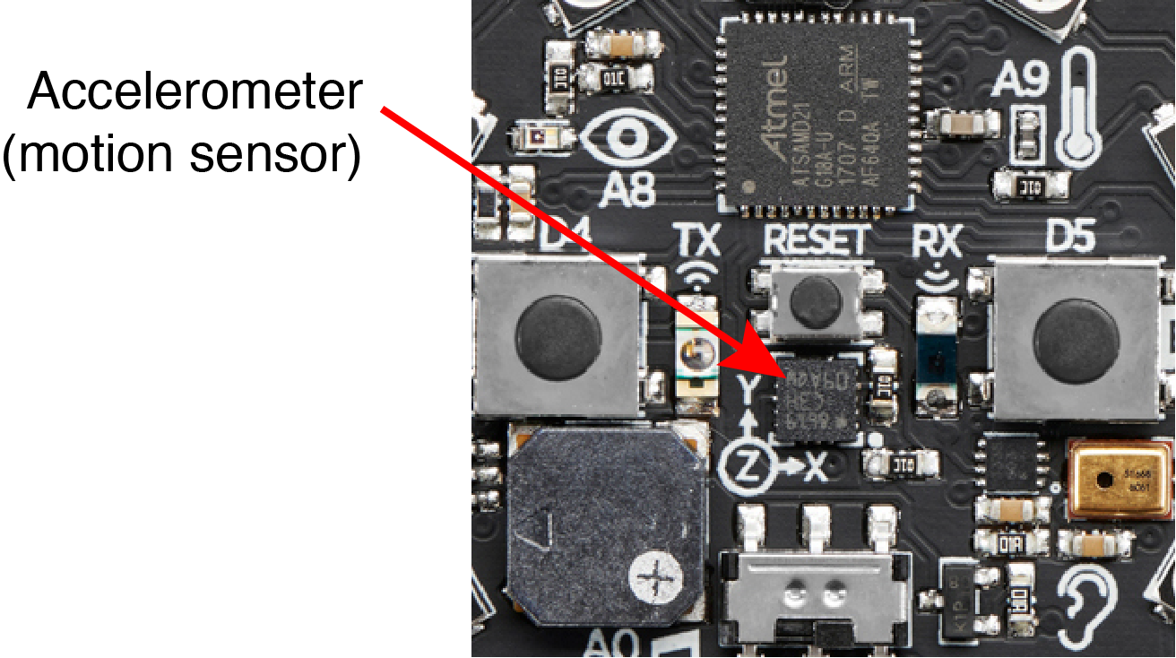
The Circuit Playground Express has an LIS3DH accelerometer mounted between the two large buttons and just below the Reset button. In the Circuit Playground documentation, the accelerometer is referred to as a motion sensor.
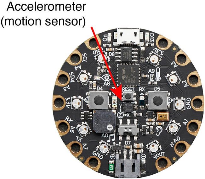
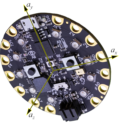
The LIS3DH measures three degrees of acceleration – one for each of the \(x\), \(y\), and \(z\) directions relative to the surface of the Circuit Playground Express. The stencil on the surface of the CPX indicates that \(x\) and \(y\) components of acceleration are in the plane of the board, and \(z\) is (by the right hand rule) pointed up from the surface. The following image shows the \(a_x\), \(a_y\) and \(a_z\) axes as an orthogonal triad of vectors emanating from the body of the accelerometer. The motion sensor independently measures the acceleration in each of those coordinate directions.
The LIS3DH chip has sensor hardware and on-board logic to detect motion events such as free-fall, tap and double-tap sensing.
The LIS3DH chip can communicate over I2C or SPI digital interfaces. Reading and processing the analog sensor data on an Arduino board is not necessary. Using the LIS3DH on the Circuit Playground Express only requires writing code because the LIS3DH is mounted directly on the Feather nRF52840 Sense board.
This web page provides a sample program for obtaining the accelerometer data with the Circuit Playground Express. The full capabilities of the LIS3DH are described in the datasheet from the manufacturer, STMicroelectronics.
Adafruit has instructions for using an external LIS3DH breakout board, an Arduino library, and support for reading the on-board sensor with the library for the Circuit Playground Express.
Upload the demo_accelerometer.ino sketch to the Circuit Playground Express
The demo_accelerometer.ino sketch shows how to read the x, y, and z components of acceleration that are measured by the LIS3DH.
Download demo_accelerometer.ino and upload it to your board. While uploading the NeoPixel on the Circuit Playground Express glows green and then red. After the upload is complete you can open the Serial Monitor to see the accelerometer data from the sensor. Make sure the baud rate of the Serial Monitor is 11520, to be compatible with he code in demo_accelerometer.ino.
//  File:  demo_accelerometer.ino
//
//  Demonstrate use of accelerometer data on a Circuit Playground.
//  Print raw (no text) values of accelerometer readings so that
//  values can be displayed on the Serial Monitor.
//
//  Gerald Recktenwald, gerry@pdx.edu,  2021-08-05

#include <Adafruit_CircuitPlayground.h>

// ------------------------------------------------------------------------------------
void setup() {
  Serial.begin(115200);
  CircuitPlayground.begin();

  while( !Serial ) delay(10);           //  Wait for USB connection
  Serial.println("ax\tay\taz\tatot");   //  Send labels for the Serial Plotter
}

// ------------------------------------------------------------------------------------
void loop() {
  float ax, ay, az, atot;   //  acceleration components and magnitude measured by the sensor

  // -- Retrieve acceleration components and compute the total
  ax = CircuitPlayground.motionX();
  ay = CircuitPlayground.motionY();
  az = CircuitPlayground.motionZ();
  atot = sqrt(ax*ax + ay*ay + az*az);   //  could also use pow(ax,2), but ax*ax is faster

  // -- Print acceleration values without extra text so that Serial Plotter can be used
  Serial.print(ax);
  Serial.print("\t");   Serial.print(ay);
  Serial.print("\t");   Serial.print(az);
  Serial.print("\t");   Serial.println(atot);

  delay(100);
}
Viewing the Accelerometer Data
When connected to your computer the demo_accelerometer.ino sketch should produce a stream of three acceleration values in the \(x\), \(y\) and \(z\)-directions. The orientation of the axes is indicated by the stencil on the board as shown in the following close-up view of the LIS3DH chip on the Circuit Playground Express that shows a stencil
Numerical data in the Serial Monitor
The following data shows typical output to the Serial Monitor when the demo_accelerometer.ino sketch is running the Circuit Playground Express is resting upright on a desk.
ax	ay	az	atot
0.07	-0.31	9.93	9.94
0.06	-0.27	9.59	9.59
0.02	-0.28	9.74	9.75
0.01	-0.30	9.91	9.92
0.04	-0.33	9.79	9.80
0.04	-0.24	9.91	9.92
0.01	-0.32	9.66	9.66
-0.11	-0.14	10.03	10.03
0.03	-0.25	9.87	9.87
The columns, left to right are the \(x\), \(y\) and \(z\) components of acceleration in units of \(\mathrm{m}^2/\mathrm{s}\). Since the board was stationary when the readings were made, the only component of acceleration that is active is the acceleration of gravity, which is \(9.81\,\mathrm{m}^2/\mathrm{s}\). The largest error in the \(z\) component data shown above is less than 3 percent.
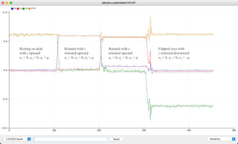
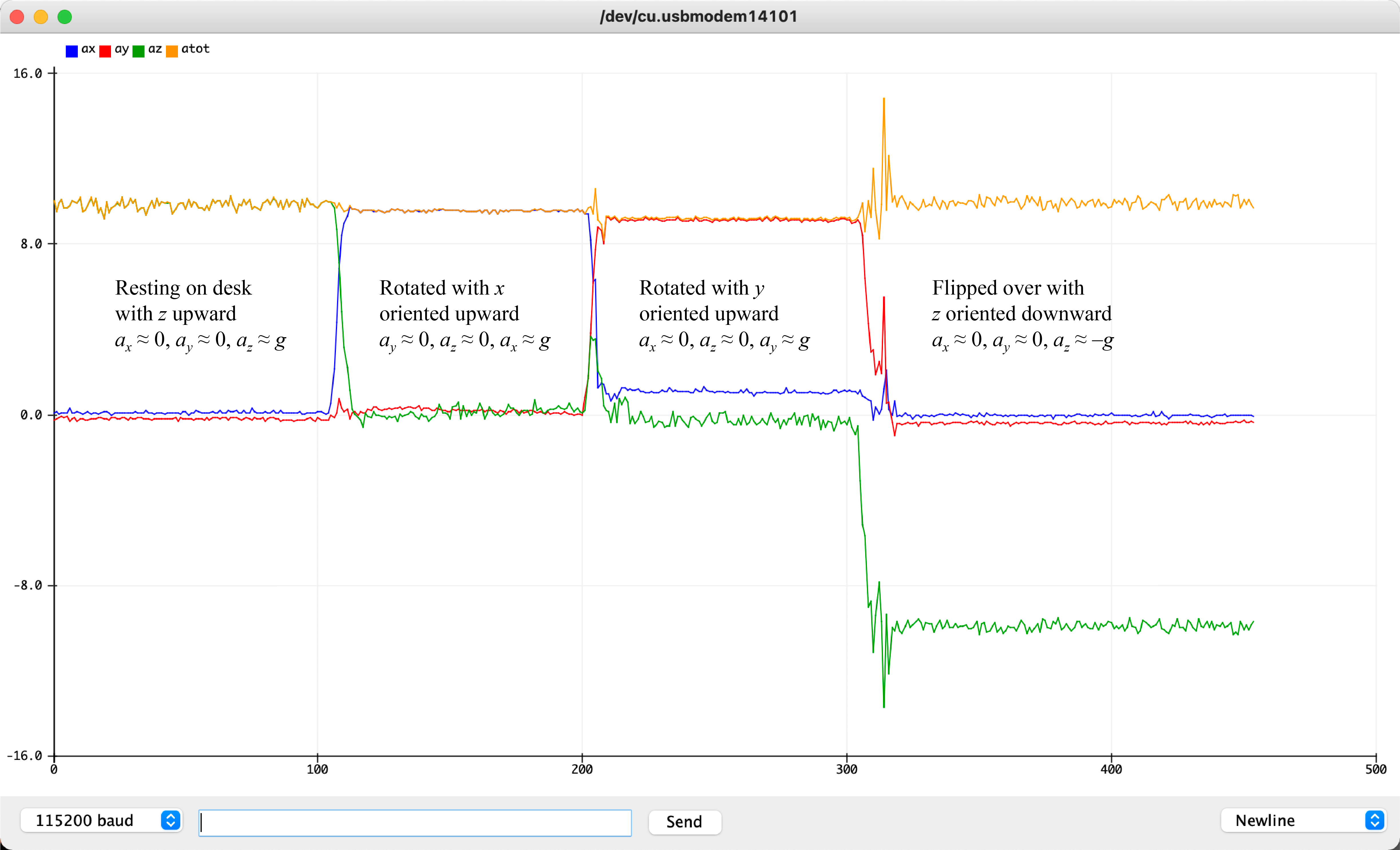
Graphical view with the Serial Plotter
Opening the Serial Plotter instead of the Serial Monitor (both cannot be open at the same time) produces an image like that below. The small color legend in the upper left corner associates blue, red and green curves with the \(x\), \(y\) and \(z\) components of acceleration. For the data shown below, the accelerometer was gently rotated about the \(x\) and \(y\) axes, which caused the magnitudes of the \(x\), \(y\) and \(z\) components of acceleration to shift.
Accelerometer Readings
In the demo_accelerometer.ino sketch, the three channels of the accelerometer are read with the following statements.
  float ax, ay, az, atot;

  ax = CircuitPlayground.motionX();
  ay = CircuitPlayground.motionY();
  az = CircuitPlayground.motionZ();
The values of ax, ay and az are the acceleration components in the \(x\), \(y\) and \(z\) directions, respectively, in units of \(\mathrm{m}/\mathrm{s}^2\).
Acceleration is a vector quantity. The magnitude of the acceleration vector is computed with
atot = sqrt( ax*ax + ay*ay + az*az );
The expression ax*ax is used instead of pow(ax,2) because multiplication is faster in this instance. Note that the C language does not have an exponentiation operator, like ^ that is available in other languages.
Board at Rest
When the board is at rest, regardless of the orientation, the total acceleration should be close to the acceleration of gravity, \(9.81\ \mathrm{m}/\mathrm{s}^2\). As shown in the image of the Serial Plotter window, above, or in the values exported to the Serial Monitor, the maximum output of the accelerometer is not equal to \(9.81\ \mathrm{m}/\mathrm{s}^2\). That is not surprising since the sensor is very low cost and is not designed for precise acceleration measurements. According to the LIS3DH datasheet, the zero-offset accuracy of the accelerometer is \(\pm 40\)g or \(0.39\,\mathrm{m}/\mathrm{s}^2\) when operating on the \(\pm2\)g range.
Despite the modest accuracy of the sensor, the acceleration data is very useful for tasks such as detecting orientation or detecting sudden movement.
Dynamic Plot of Total Acceleration on an OLED
If the Circuit Playground Express is connected to an 128x64 OLED the OLEDdrawPlotAcceleration.ino sketch will create a dynamic plot of total acceleration.
Using the Accelerometer to Indicate Orientation
When the accelerometer is stationary, or moving slowly, the output of the accelerometer can be used to indicate the orientation of the Circuit Playground with respect to gravity. Orientation data is useful in many applications such as a digital level that indicates whether a surface is horizontal or vertical, or in a game interface that uses tilt to steer a physical or virtual object. We present two simple examples that use the orientation of the Circuit Playground to turn NeoPixels on and off.
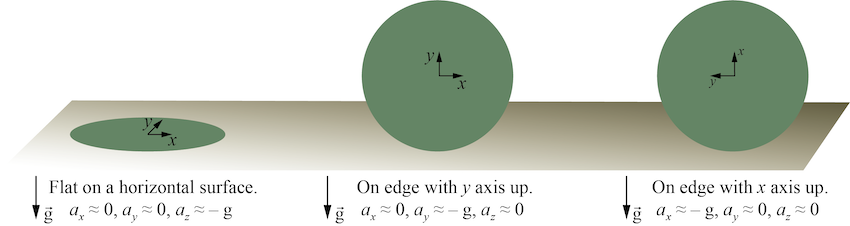
Basic Orientations
The following schematic shows a model of the Circuit Playground in three primary orientations, each with one of the axes of the accelerometer parallel to the gravity vector. By comparing the magnitude of \(a_x\), \(a_y\) and \(a_z\) to the acceleration of gravity, we can infer the orientation. For example, when the magnitude of \(a_z\) is close to negative \(g\), we infer that the Circuit Playground is resting on a horizontal surface with the face of the Circuit Playground oriented upward.
fliplight.ino Sketch
The fliplight.ino sketch demonstrates how the accelerometer reading can be used to control another action. In this case, all of the NeoPixels are turned on whenever the face of the Circuit Playground is oriented downward, i.e. whenever \(a_z<0\).
Download fliplight.ino. and experiment with different orientations.
fliplight_angle.ino Sketch
The fliplight_angle.ino sketch is a modification of the fliplight.ino sketch such that the NeoPixels are turned on only when the Circuit Playground has a limited range of downward tilts. Implementing this criterion requires a quick calculation using the geometry of vectors in three-dimensional space.
As shown in the following image, when the Circuit Playground is in an arbitrary orientation there is an angle \(\theta\) between the gravity vector and the \(a_z\) component measured by the accelerometer.
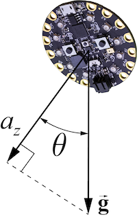
When the Circuit Playground is stationary (or moving very slowly), the \(a_z\) reading will be the component of the gravity vector projected onto the (local) \(z\) axis of the accelerometer. Using trigonometry in the plane shared by \(\vec{g}\) and the \(z\) axis we get
\[a_z = g \cos \theta\]Solving for \(\theta\) gives
\[\theta = \cos^{-1}\left( \frac{a_z}{g} \right)\]Also when the Circuit Playground is stationary (or moving slowly), the total acceleration measured by the accelerometer is equal to the acceleration of gravity. Thus, (when the Circuit Playground is stationary)
\[g = \sqrt{a_x^2 + a_y^2 + a_z^2}\]Substituting this expression for \(g\) into the formula for \(\theta\) gives
\[\theta = \cos^{-1}\left( \frac{a_z}{\sqrt{a_x^2 + a_y^2 + a_z^2}} \right)\]The preceding formula allows us to compute the angle between the \(z\) axis of the Circuit Playground and the gravity vector.
The fliplight_angle.ino sketch uses a criterion on the magnitude of \(\theta\) to determine when the NeoPixels are turned on. The following excerpt shows the key lines in the loop function of fliplight_angle.ino.
float delta_theta = 30.0;  //  difference in angle that determines whether NeoPixels are turned on

// -- Retrieve acceleration components and compute the total
ax = CircuitPlayground.motionX();
ay = CircuitPlayground.motionY();
az = CircuitPlayground.motionZ();
atot = sqrt(ax*ax + ay*ay + az*az);   //  could also use pow(ax,2), but ax*ax is faster

theta = (180.0/PI) * acos(az/atot);   //  180/PI converts radians to degrees

// -- Turn all NeoPixels on only when theta is within delta_theta of 180
if ( abs(180.0 - theta) < delta_theta )  {
  setAllNeoPixels(255,255,255);             //  All on, white
} else {
  setAllNeoPixels(0,0,0);                   //  All off
}
Download fliplight_angle.ino. and experiment with different orientations of the Circuit Playground and different values of delta_theta.
Using the Accelerometer to Count Steps
Phones and wearable devices are widely available to monitor and measure your activity. A common measure is the number of steps you take while wearing the device. The accelerometer on the Circuit Playground Express can be used to create a step counter, also known as a pedometer.
We have created a set of slides you can download describing the pedometer algorithm.
The slides refer to a series of sketches that demonstrate the concepts used in a step-counting algorithm. Those sketches are collected in the following links.
OLEDdrawPlotAcceleration.inocreates a dynamic plot of total acceleration on a 128x64 OLEDdemo_accelerometer_smoothed.inoshows how to use exponentially-weighted average as a low-pass filterOLED_pedometer_v1.inouses the basic step counting algorithmOLED_pedometer.inouses a modification to the step counting algorithm that ignores quick motions
We recommend using the OLED_pedometer.ino (last link in list) sketch as the basis for creating your own step counter.