Micro-OLED Display
Small Organic Light-Emitting Diode (OLED) displays are relatively inexpensive devices for text and graphical output from an Arduino board. This web page demonstrates how to connect a 128 x 64 micro OLED display from Adafruit to the Adafruit Circuit Playground Express.
- Mounting the OLED to the CPX with a 3D-printed bracket
- Install the Adafruit SSD1306 Library
- Run the
ssd1306_128x64_i2c.inosketch from the Adafruit Library - Run
OLEDdisplayFunctions.inoto display internal clock time - Run
OLEDambientLight.inoto display ambient light levels - Run
OLEDdrawPlotAcceleration.inoto plot total acceleration - Coordinate system for the OLED display
- Using the
Fmacro to save SRAM
Mounting the OLED to the CPX with a 3D-printed bracket
The OLED can be attached to the Circuit Playground Express with a 3D-printed bracket, as shown in the following image. This web page (the one you are reading) has high-level instructions for attaching the bracket and OLED to the CPX. More details are available in a PDF version of presentation slides.
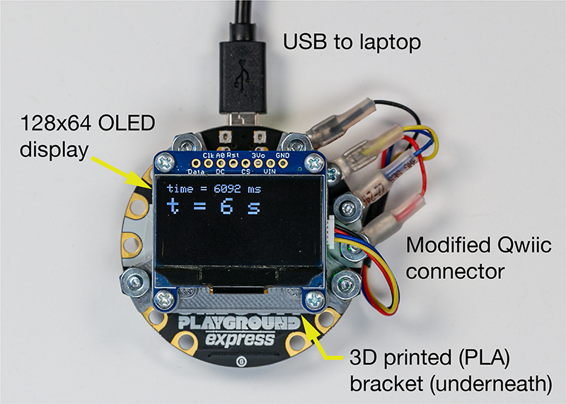
The bracket is designed to attach to the smooth side of the CPX with four #4 screws. The OLED is attached to the bracket with four #2 sheet metal screws. The electrical connection between the CPX and the OLED is made with a modified, 100mm Qwiic cable.
The bracket has enough vertical space to hold a small LiPo battery under the OLED. This battery sold by Adafruit should fit.
The following image shows a solid model of the bracket with the reference geometry (in dashed lines) of the CPX.
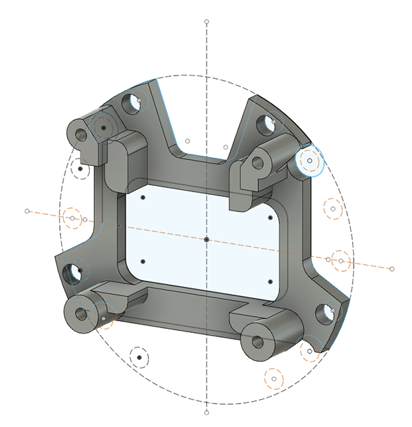
You can download the Fusion360 model of the bracket and/or download the STL model of the bracket to print your own copy.
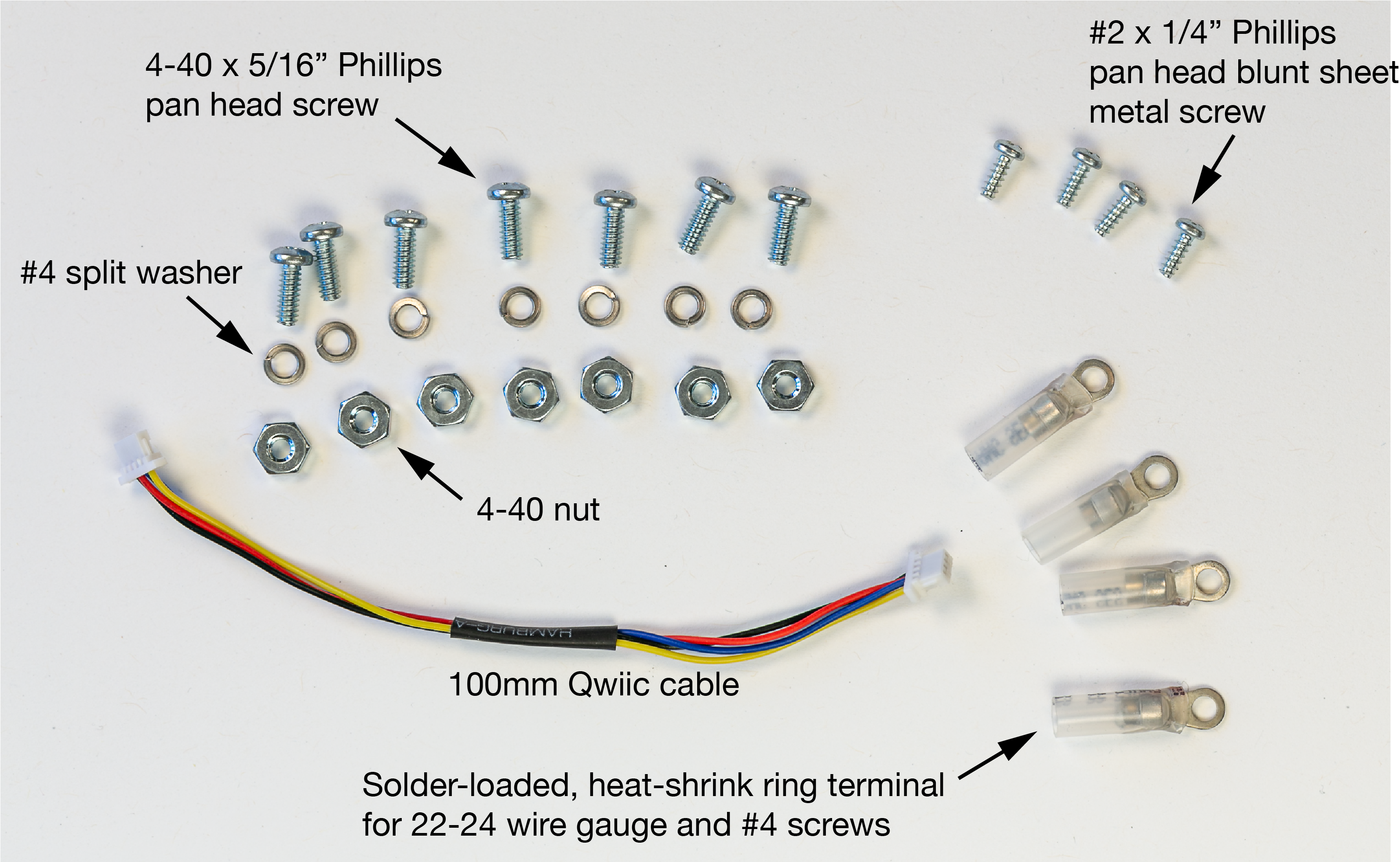
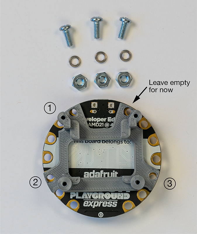
The following image shows the hardware parts in the assembly, not including the 3D-printed bracket.
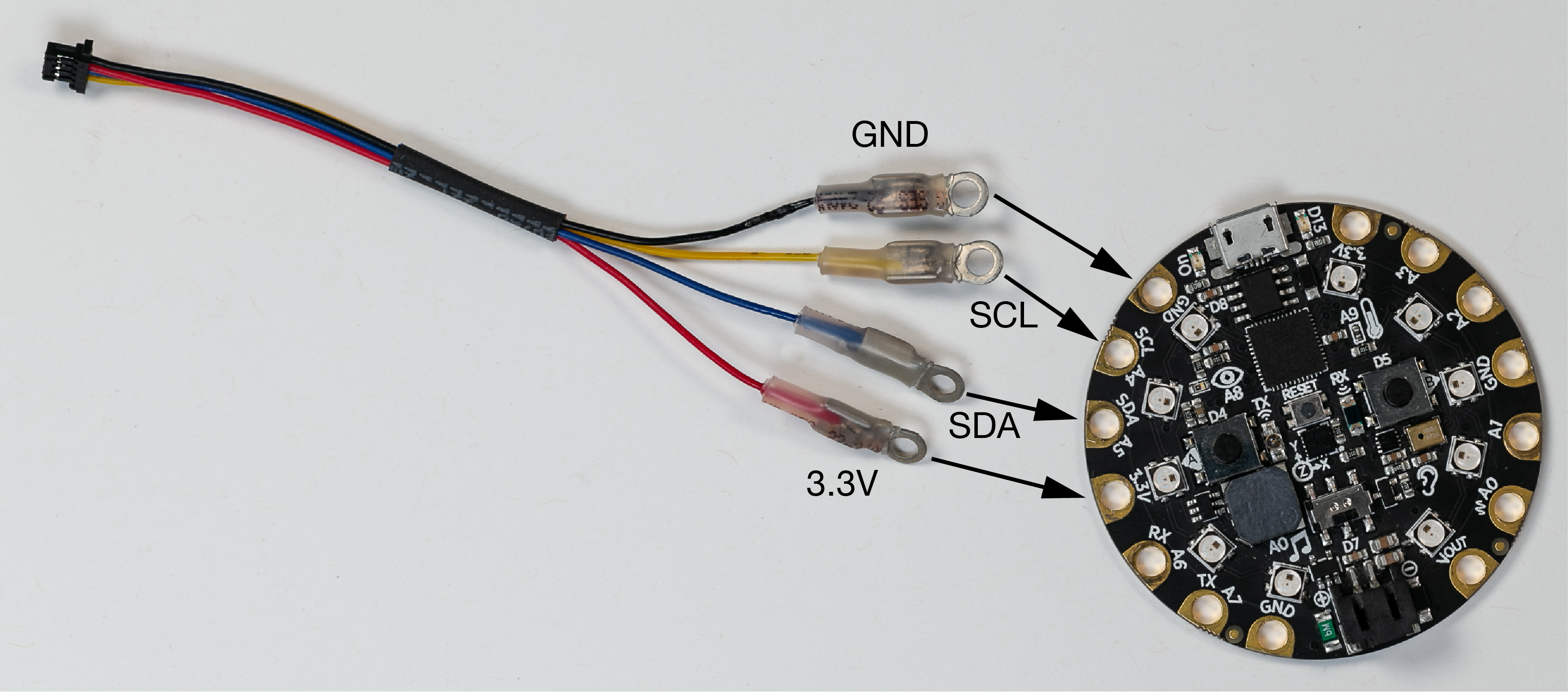
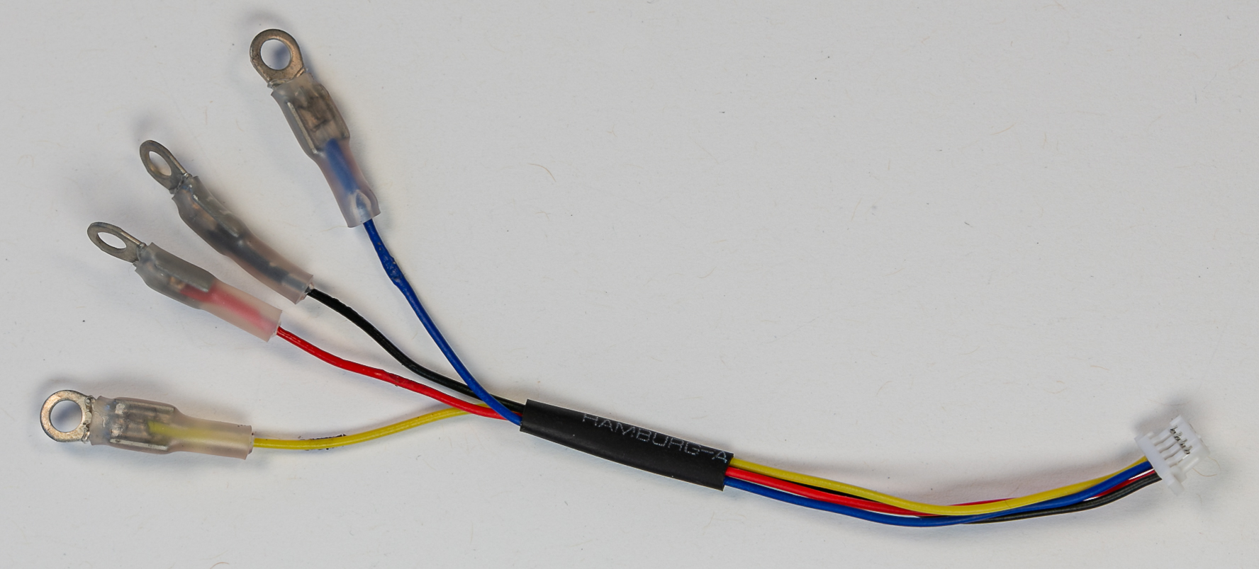
The JST connector on one end of the Qwiic cable was removed and round terminals were attached to the four wires. The following image shows the pattern for connecting the modified Qwiic cable to the Circuit Playground Express. This photo is only intended to show which end of the modified Qwiic cable is attached to which pads on the CPX. The following instructions show the sequence of steps for making the attachment.
The high-level steps to assemble the parts are
- Cut the JST connector from one end of the Qwiic cable. Strip about 2mm of the just-cut wires for Power (red), GND (black), SCL (yellow) and SDA (blue) of the Qwiic cable.
-
Use a heat gun to attach the solder-loaded, heat-shrink ring terminals
-
Use three 4-40 screws, nuts and split washers to attach the bracket to the CPX. The split washer should be placed under the head of the nut. Do not tighten the screws too much, and do not attach the fourth 4-40 screw to the pad corresponding to the GND pad next to the USB socket.
- Attach the SCL, SDA and power (3.3V) terminals to the CPX.
- Orient the screws for the SDA (blue) and power (red) terminals so that the nut is on the side with the 3D-printed bracket
- Orient the screw for the SCL (yellow) terminal in the opposite direction from the screws for SDA and power. In other words, the screw head will be on the same side of the CPX as the bracket. This orientation of the screw should be obvious because a 4-40 nut will not fit into the space on the bracket side of the CPA.
- Slide the ground terminal into the gap between the bracket and the GND pad of the CPX. Align the hole in the terminal with the hole in the bracket. (This is the fourth hole in the bracket that was not attached in step 1, above.)
- Insert a 4-40 screw to clamp the ground terminal between the CPX and the bracket. The screw should be oriented so that the nut is on the bracket side of the CPX.
- Attach the OLED to the bracket with the four #2 sheet metal screws. Do not over-tighten those screws so that you would avoid (1) stripping the 3D-printed material of the bracket, or (2) possibly cracking the OLED screen
- Very carefully insert the JST end of the Qwiic cable into the socket on the OLED.
Install the Adafruit SSD1306 Library
To use the monochrome 128 x 64 micro OLED, you first need to install the Adafruit SSD1306 Library and the Adafruit GFX Library. The following steps with the Library Manager assume that you have properly configured the board support via the Arduino IDE Preferences.
From menu at the top of the Arduino IDE, select Sketch –> Include Library –> Manage Libraries…
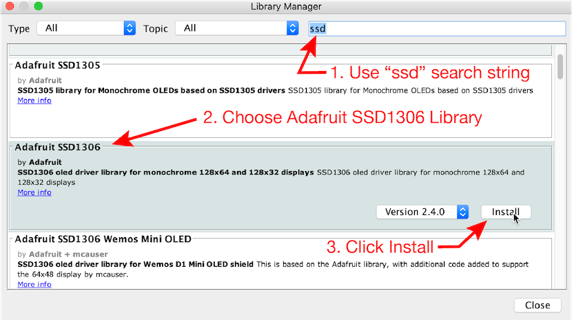
- Enter “ssd” in the search box to narrow the range of choices. Or, if you prefer, scroll through the entire list of libraries (not recommended).
- Choose the “Adafruit SSD1306” panel, which will cause the Install button to become visible.
- Click Install.
- The installer should ask if you want to install other dependent libraries, and you should check all the boxes of dependent libraries.
- After installing the SSD1306 library, check to see that the GFX library was also installed. If not, repeat steps 1 - 3 with these exceptions
- Search for “GFX”
- Install the “Adafruit GFX Library”
Run the ssd1306_128x64_i2c.ino sketch from the Adafruit Library
The Adafruit SSD1306 library includes example sketches to demonstrate features of the micro OLED display. The variants of the examples are appropriate for different types of connections and different size OLED displays.
Using the menus at the top of the Arduino IDE, select File –> Examples –> Adafruit SSD1306 –> ssd1306_128x64_i2c. Upload that sketch to the Feather board.
If you have connected the STEMMA QT cable to the correct pads on the Circuit Playground Express, the ssd1306_128x64_i2c.ino should run and display graphical and text images on the OLED board.
Run OLEDdisplayFunctions.ino to display internal clock time
The OLEDdisplayFunctions.ino displays the internal clock time in milliseconds and microseconds on the 128x32 OLED. The internal clock is restarted each time the microcontroller board is reset, or supplied with power after being disconnected from power.
Download the OLEDdisplayFunctions.ino sketch
The purpose of OLEDdisplayFunctions is simply to show how to start the OLED display and dynamically update that display with new data. The internal clock time is just a convenient data source.
The Functions in OLEDdisplayFunctions refers to the use of C++ functions in the sketch to isolate the OLED-related tasks. The setupOLED function starts the connection between the external OLED panel and the running sketch. The updateOLED function accepts the time in milliseconds and seconds as inputs, and creates a display of those values on the OLED screen. The use of functions to compartmentalize tasks is strongly encouraged.
Run OLEDambientLight.ino to display ambient light levels
The OLEDambientLight.ino sketch reads the on-board light sensor of the CPX and displays the time and light level on the OLED. You could substitute reading from the on-board temperature sensor or the on-board accelerometer with suitable changes to the code in OLEDambientLight.ino
Download the OLEDambientLight.ino sketch
Run OLEDdrawPlotAcceleration.ino to plot total acceleration
The OLEDdrawPlotAcceleration.ino sketch reads the on-board accelerometer of the CPX and displays a continuous line plot of the total acceleration.
Download the OLEDdrawPlotAcceleration.ino sketch
Coordinate system for the OLED display
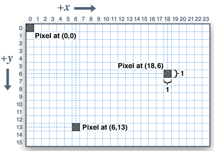
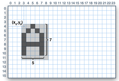
The OLED display is an addressable grid that is 128 pixels wide by 64 pixels high. Before adding a character or number (converted to characters) to the buffer, you will need to specify the starting position of the upper left corner of the character (or number).
Pixel locations on the OLED display are specified as (x,y) coordinates where x is the horizontal position and y is the vertical position measured downward
 Source: learn.adafruit.com/adafruit-gfx-graphics-library
To locate a character on the display, specify the (x,y) coordinates of the upper left corner of that character.
 Source: learn.adafruit.com/adafruit-gfx-graphics-library
The letter “A” in the preceding image would be added to the display buffer with the following code
OLED.setCursor(3,4);
OLED.display("A");
Using the F macro to save SRAM
Throughout the sample codes are expressions like
OLED.print(F("OLED is ready"));
What is the F( ) expression? Why does it appear in code related to the OLED display?
A string to be displayed on the OLED is wrapped in a F( ... ) expression. The F() is a macro (acts somewhat like a function, but it’s not a function) that copies the enclosed string to the same memory space on the Arduino board that is used by the program code. The net effect is to preserve memory (on-board SRAM) for use by Arduino sketch while it is running.
Just treat the F( ) construct as a necessary way of writing fixed strings to the OLED display. By ‘‘fixed’’ strings we mean a string that does not change while the sketch is running.
Recommendations
- As general practice, use the
F( )macro to reduce memory consumption. - The Circuit Playground Express has sufficient memory that the
F( )macro is usually not critical for codes on the Circuit Playground Express. However, if you move your code to another Arduino board that has less RAM, you may experience bugs that are very hard to understand and fix. - Do not use
F( )around numerical variables. The benefit ofF( )comes from moving strings that do not change into PROGMEM, thereby preserving SRAM.
References
- https://arduino.stackexchange.com/questions/19330/store-string-using-f-macro
- https://www.baldengineer.com/arduino-f-macro.html
- https://forum.arduino.cc/index.php?topic=91314.0