A hacked inkjet printer is used to demonstrate electromechanical control of small DC motors. The system responds to limit switches and uses a TB6612 breakout board to drive the printer's motors. The electrical circuit and software is implemented with an Arduino UNO microcontroller.
To follow along on this example you probably want to download these files:
motor_pong.inoArduino program that uses the MME Motor Library- MMEmotor library (zip archive) provides an object-oriented interface to the TB6612 breakout board. Refer to the Arduino documentation for instructions on installing a library.
- Our local TB6612 wiring guide
These additional resources will also be helpful:
- Adafruit's tutorial
- Sparkfun's TB6612FNG Hookup Guide
- Our TB6612 wiring guide
The goal of this web page is to demonstrate how the two DC motors in an old inkjet printer can be controlled with an Arduino and an H-bridge chip. The Toshiba TB6612 dual H-bridge is used, though there are several alternatives. Likewise, one could use a variety of microcontrollers.
motor_pong.ino is an Arduino program
that causes the inkjet carriage — the structure that holds the ink cartridges —
to move back and forth indefinitely. This is only a technology demonstration
for educational purposes, not an otherwise practical goal.
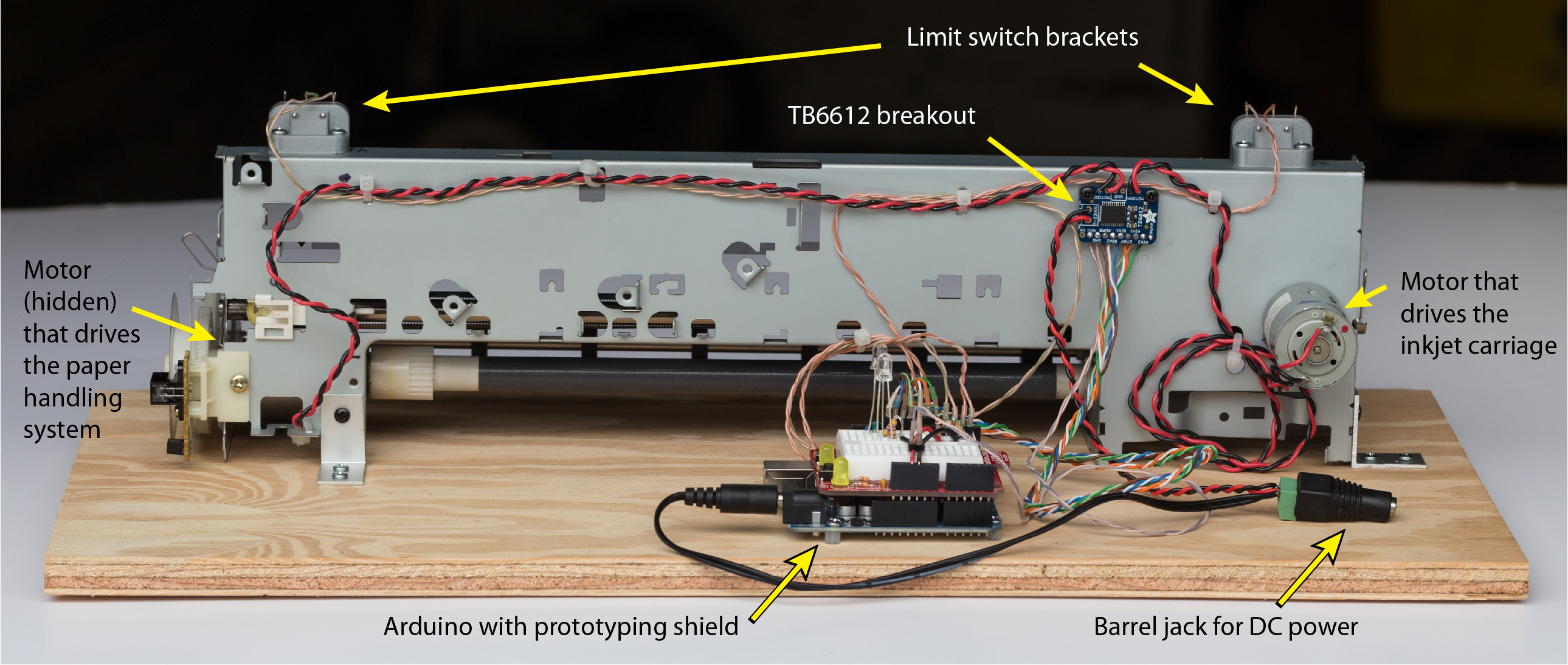
Hacked Printer Carcass
An inkjet printer was stripped down to its sheet metal frame and its two motion control systems: one for the print head and one for the paper advancement system. Care was taken to preserve the bearings, motor supports and position encoders. For the current project, only the motors, the mechanical drive system and bearings, and the inkjet carriage are used. Figure 1 is an annotated photo of the back side of the stripped-down printer. The inkjet carriage is on the opposite side

The printer carcass and an Arduino UNO with prototype shield are secured to a plywood board. A TB6612 breakout board is attached to the metal frame with sheet metal screws and nylon standoffs. Two microswitches scavenged from another device are mounted to the frame with 3D printed brackets. A DC barrel jack connects a 12VDC power supply (not shown in the photo) to the power input tabs on the TB6612. The 12V supply is also connected in parallel to another male barrel jack that supplies 12V power to the Arduino UNO.
TB6612 Wiring
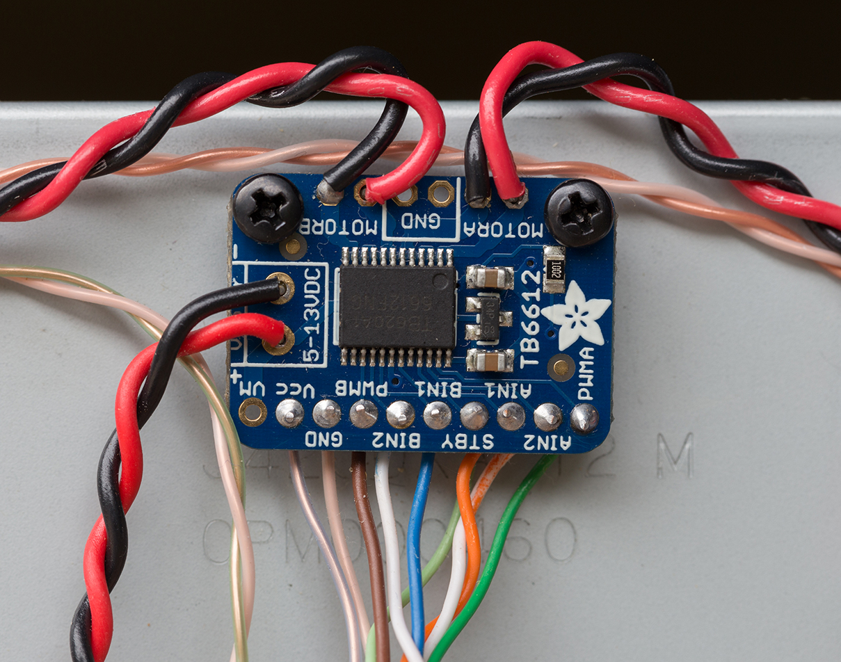
Figure 2 shows the wiring of the TB6612 breakout board. The red and black wire pairs carry current to the motors. Logic level signals are connected with twisted pairs from scrap CAT-5E cable. Refer to the TB6612 wiring guide for a more detailed description of the pins on the TB6612.
The following table shows the pin assignments for the Arduino UNO to drive the
TB6612. The physical pin connections on the prototype shield must be consistent
with the pin addresses used in the
motor_pong.ino Arduino program.
    TB6612   |  Arduino   |
    Contact  |    pin     |  Wire color
   ----------------------------------------
     PWMA    |    D5      |  dark green
     AIN1    |    D6      |  orange
     AIN2    |    D7      |  white/orange
             |            |
     STDBY   |    D8      |  light green
             |            |
     PWMB    |    D9      |  brown
     BIN1    |    D10     |  blue
     BIN2    |    D11     |  white/blue
The following excerpts from motor_pong.ino
demonstrate how the wiring and Arduino code are aligned.
// Logic pins to control the motors: PWMA and PWMB must be pins capable
// of PWM output.  The user needs to correctly wire these pins to the
// corresponding contacts on the TB6612 breakout
#define PWMA 5  // Motor A
#define AIN1 6
#define AIN2 7

#define STBY 8   // Standby pin of TB6612. Shared by both channels

#define PWMB 9   // Motor B
#define BIN1 10
#define BIN2 11

// -- Initialize MMEmotor objects that control motors that drive
//    the paper rollers and the inkjet carriage
MMEmotor paperMotor  = MMEmotor(BIN1, BIN2, PWMB, STBY);
MMEmotor inkJetMotor = MMEmotor(AIN1, AIN2, PWMA, STBY);
Motor Control
After the paperMotor and inkJetMotor objects are instantiated, the motors
can be controlled by one of the following methods defined by MMEmotor.h and MMEmotor.cpp in the
MMEmotor library.
void brake();
void off();

void forward(int speedVal);
void forward();
void backward(int speedVal);
void backward();

void moveAtSpeed(int speedVal);
void reverse();
void standby();

int getSpeed();
int getDirection();
In the setup function of motor_pong.ino,
the inkjet motor is started at 59% (=150/255) of full speed.
void setup() {

//  ... other lines of code not included here

  inkJetMotor.forward(150);   // argument is speed:  0 <= speed <= 255
}
After the initial motor speed is set, the state of the inkJetMotor is changed
only in the two interrupt service routines (handle_interrupt_A and
handle_interrupt_B) that respond to interrupts from the microswitches. When an
interrupt is detected, the motion of the carriage is reversed with one line
inkJetMotor.reverse(); // Reverse motor direction
The reverse method in MMEmotor.cpp keeps track of the direction before and
after reverse is executed.
Microswitches to Limit Motion
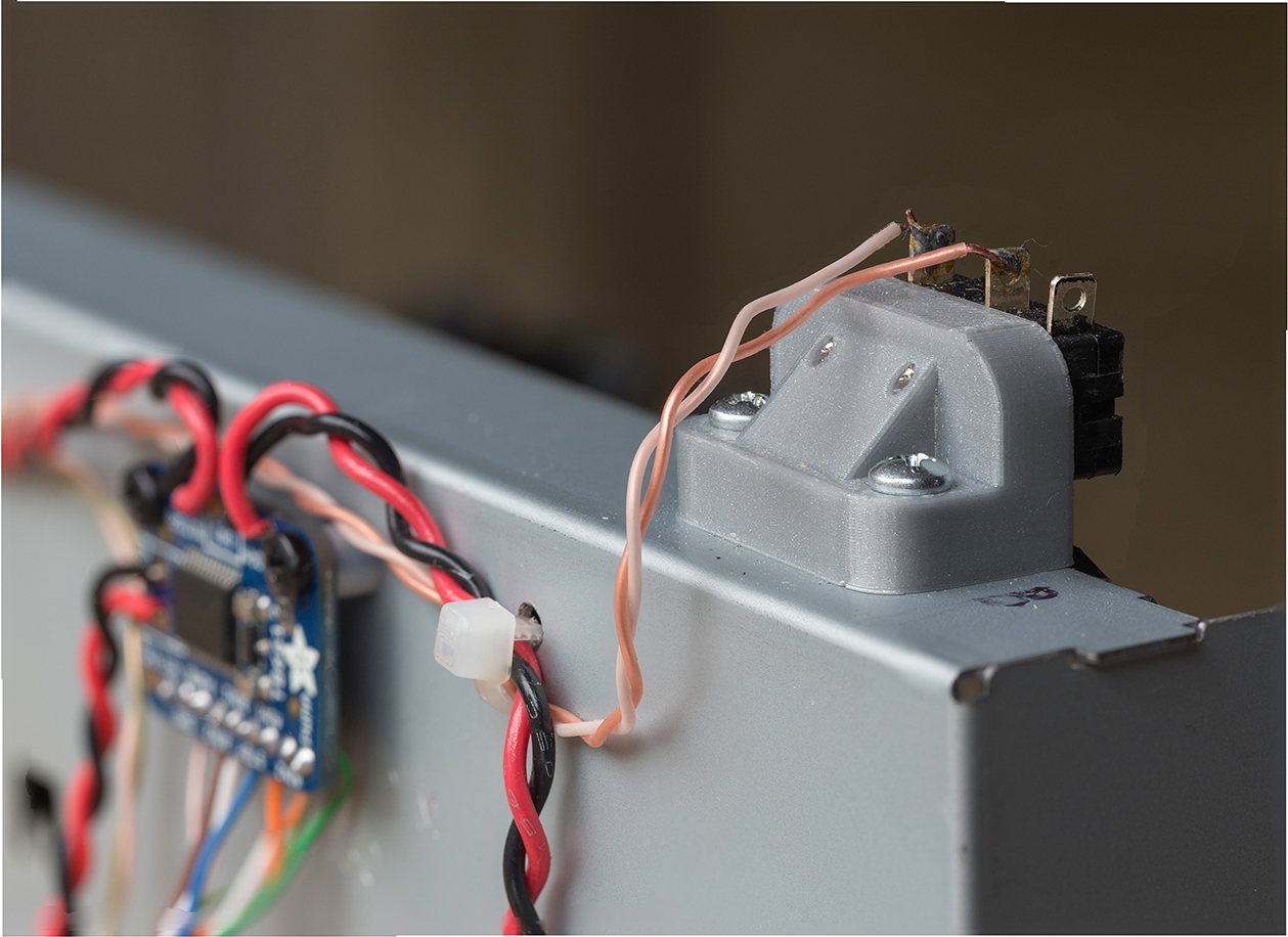
Two microswitches were scavenged from another device and attached to the printer frame. Each microswitch is mounted on with a small, 3D printed part that positions the microswitch so that it is engaged when the carriage reaches the desired end of travel. Figure 3 shows the 3D printed part and wires connected to one of the microswitches.
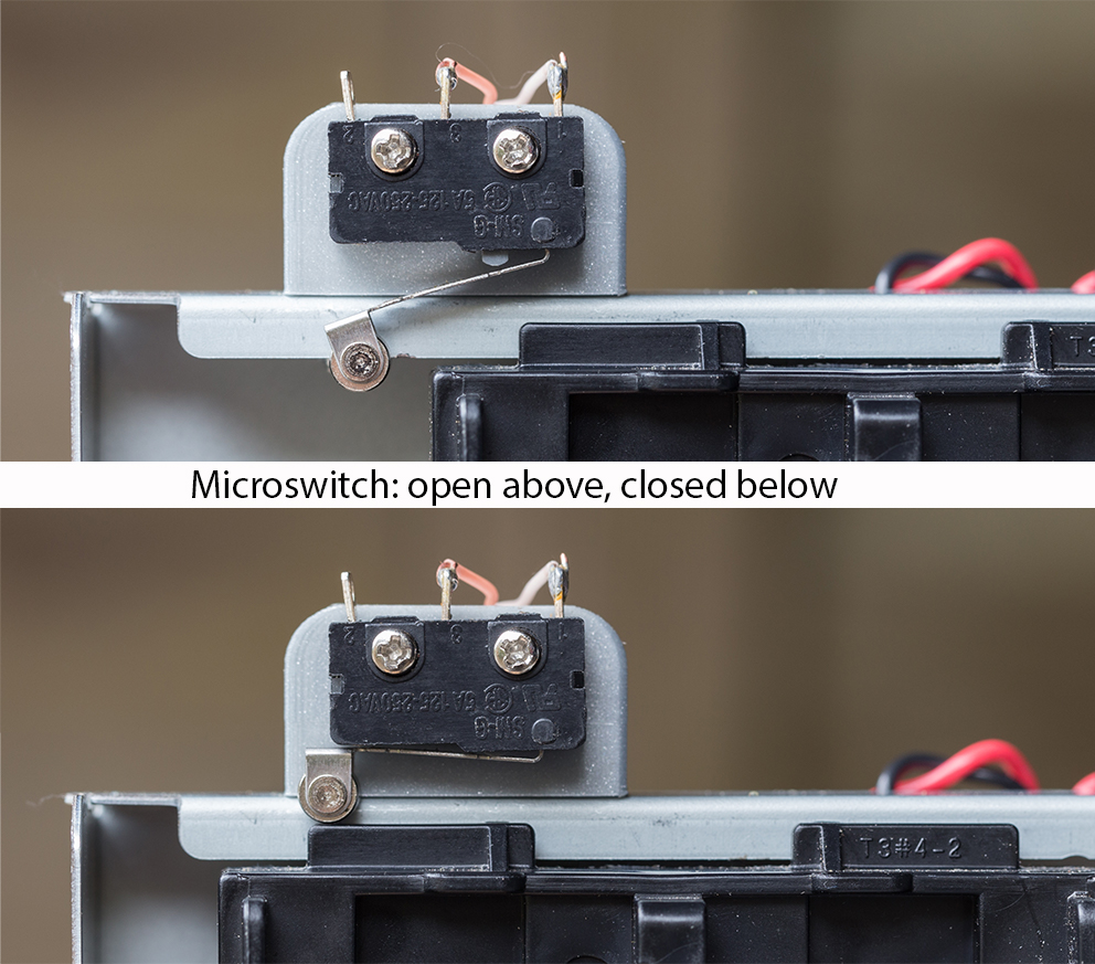
Without the feedback from the microswitches, which are wired into the Arduino, the motor would continue to drive the carriage beyond a safe end of travel position, which would crash the carriage into the support and could damage the drive belt, motor and possibly overload the motor driver. The following photo is a close-up of the microswitch assembly labeled "B" on one end of the printer frame. The microswitch at the other end is labeled "A".
The microswitches are actuated when the printer carriage approaches the end of its rod bearing. Figure 4 shows microswitch B in it's open and closed position.
The two normally open (NO) terminals of the microswitches are connected to one of the two interrupt pins (D2 or D3) of the Arduino UNO microcontroller. The interrupt pins are biased high with 10k pull-up resistors as shown in Figure 5.

The microswitches signal that the printer carriage has reached the end of travel. The Arduino code responds to the signal by reversing direction of the motor that drives the inkjet carriage.
Configuration and use of the interrupts is controlled by the following global
variables in motor_pong.ino.
// -- Data used to configure interrupt pins.  See attachInterrupt()
#define  LIMIT_A_PIN  2         //  I/O pin for interrupt on switch A
#define  LIMIT_B_PIN  3         //  I/O pin for interrupt on switch B
#define  SWITCH_A_INTERRUPT 0   // Interrupt number 0 is on pin 2
#define  SWITCH_B_INTERRUPT 1   // Interrupt number 1 is on pin 3

// -- limit_A_tripped and limit_B_tripped are flags indicating
//    state of the limit switches.  True if a limit switch has
//    been tripped. False otherwise
volatile bool limit_A_tripped = false;
volatile bool limit_B_tripped = false;
The interrupts are configured in the setup function of
motor_pong.ino.
void setup() {

  attachInterrupt(SWITCH_A_INTERRUPT, handle_interrupt_A, FALLING);
  attachInterrupt(SWITCH_B_INTERRUPT, handle_interrupt_B, FALLING);

//  ... other lines of code not included here

}
Here is the interrupt handler code for switch "A" mounted on one end of the printer frame. Switch "B" on the other end of the frame has the same code, but is attached to a different interrupt pin. Notice the software debouncing of the switch uses a 200 ms delay.
void  handle_interrupt_A()
{
  static unsigned long last_interrupt_time = 0;  //  Zero only on startup

  unsigned long interrupt_time = millis();       //  Always read the clock

  //  -- Ignore events separated by less than 200 msec
  if ( interrupt_time - last_interrupt_time > 200 ) {
    limit_A_tripped = true;
    digitalWrite(LEDA, HIGH);    // Turn on LED to indicate switch A
    inkJetMotor.reverse();       // Reverse motor direction
  }
  last_interrupt_time = interrupt_time;  // Save for next debounce check
}
Note that with a change in wiring, both microswitches could be connected to a single interrupt that would cause the motor to reverse direction. Combining the limit switch interrupts would free up an interrupt pin that could then be used to monitor another input, e.g. a button. You could also use a different microcontroller that has more than two interrupts.
Responding to Interrupt States in the loop Function
The interrupt handlers respond to the change in state of the limit switches. Interrupt handlers need to be fast and limited to simple actions so that they can complete their tasks before other interrupt events and not block other portions of code.
The loop function has code that is not as time critical as the code in
the interrupt handler. Here is the complete loop function in
motor_pong.ino.
void loop() {

  int LED_delay = 300;
  int paper_motor_speed = 140;

  if ( limit_A_tripped ) {
    paperMotor.forward(paper_motor_speed);
    delay(LED_delay);
    digitalWrite(LEDA, LOW);
    paperMotor.brake();
    limit_A_tripped = false;
  }

  if ( limit_B_tripped ) {
    paperMotor.backward(paper_motor_speed);
    delay(LED_delay);
    digitalWrite(LEDB, LOW);
    paperMotor.brake();
    limit_B_tripped = false;
  }

}
loop consists of two conditional code blocks that are executed only if one of
the limit switches has been tripped, as indicated by the state of
limit_A_tripped or limit_B_tripped. If one of the limits is tripped, the
code waits LED_delay milliseconds and then turns the appropriate LED off.
Note that the LED was turned on in the interrupt handler.
While waiting LED_delay milliseconds, the paper motor spins forward if limit
switch A was tripped, or backward if limit switch B was tripped. Note that
spinning the paper handler motor has no useful purpose. It, along with the LED
display, are indicators that the limit switch interrupt is waiting to be reset.
Before resuming normal execution, reset
the interrupt flag limit_A_tripped or limit_B_tripped.
LEDs to Indicate Limit Switch Activation
Two LEDs are wired to digital output pins 12 and 13 of the Arduino UNO. The LEDs are only indicators used to verify that the limit switches have activated their respective interrupt. The LED circuits were developed as an aid in debugging the hardware and software, and were implemented before the motor was circuit was connected.
Figure 6 shows the standard LED circuit. The 470 ohm current limiting resistor is necessary to avoid burning out the LEDs with the 5V logic level supplied by the Arduino UNO.
