This page provides information on hooking up a TB6612 breakout board from Adafruit, Sparkfun or Pololu.
Resources
- Adafruit's tutorial
- Sparkfun's TB6612FNG Hookup Guide.
- The MMEmotor library (zip archive) simplifies the writing of Arduino programs to control a TB6612 breakout board. Version 0.91 of the library includes two more example codes.
- TB6612 data sheet
Pinouts
Rather than use the bare TB6612 chip, I recommend the breakout boards from either Adafruit, Sparkfun or Pololu. The breakboard boards have solder pads on standard 0.1 inch pitch that match male headers that fit into standard breadboards. Or you can solder hook-up wires directly to the breakout board.
Here is a photo of the TB6612 breakout board with male headers sold by Adafruit:
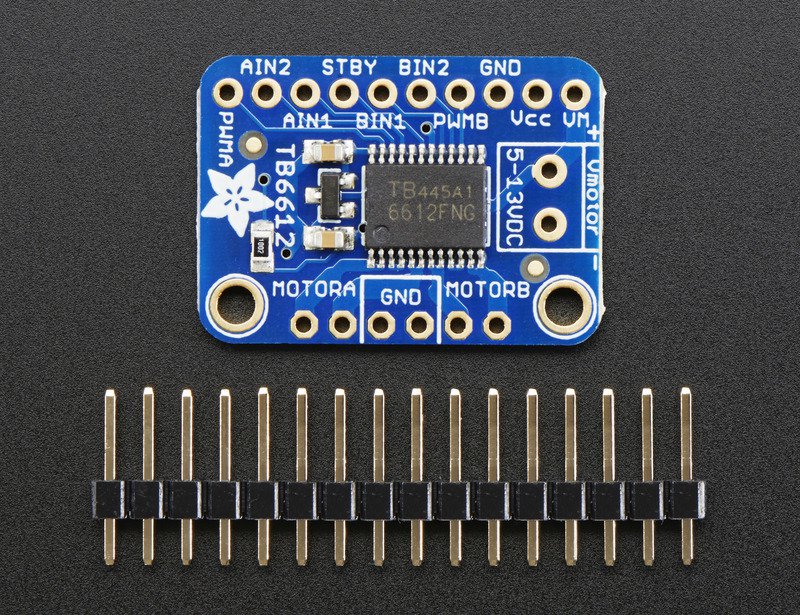
There are three types of pins on a TB6612 breakout board: power input pins, signal logic pins, and motor output pins. The following documentation is based on the Adafruit tutorial, but it should also be helpful if you have one of the Sparkfun or Pololu versions of the TB6612 breakout board. Also refer to Sparkfun's TB6612FNG Hookup Guide.
Power Pins
The Vmotor and GND pins provide electrical power that the TB6612 chip
passes on to the one or two motors attached via the motor output pins (see below).
Vcc is a 3.3V to 5V supply, referenced to the GND pin, that powers
the logic circuits in the TB6612 chip.
Vmotor line supplies the current to each of the motors
The Vcc line uses a relatively small amount of current.
From the Adafruit tutorial:
Vmotor - This is the voltage for the motors, not for the logic level. Keep this voltage between 4.5V and 13.5V. This power supply will get noisy so if you have a system with analog readings or RF other noise-sensitive parts, you may need to keep the power supplies seperate (or filtered!)
Vcc - this is the voltage for the logic levels. Set to the voltage logic you'll be using on your microcontroller. E.g. for Arduinos, 5V is probably what you want. Can be 2.7V to 5.5V so good for 3V or 5V logic
GND - This is the shared logic and motor ground. All grounds are connected
Signal Logic Pins
The Signal Logic Pins are Vcc level (i.e. 3.3V or 5V) voltage signals that
control how the TB6612 sends power to the two motors.
Refer to the logic control table at the bottom of the page and the code in
MMEmotor.cpp in the MMEmotor library
to see how combinations of HIGH and LOW on the signal logic pins control the
rotation of the motors.
From the Adafruit tutorial:
AIN1, AIN2 - these are the two inputs to the Motor A H-bridges
PWMA - this is the PWM input for the Motor A H-bridges, if you don't need PWM control, connect this to logic high.
BIN1, BIN2 - these are the two inputs to the Motor B H-bridges
PWMB - this is the PWM input for the Motor B H-bridges, if you don't need PWM control, connect this to logic high.
STBY - this is the standby pin for quickly disabling both motors, pulled up to Vcc thru a 10K resistor. Connect to ground to disable.
Motor Out Pins
These are power outputs that should be compatible with the voltage requirements
of the motor. The level of Vmotor from the external supply will set the maximum
voltage supplied to the motors. PWM is used to control the effective power/voltage
to the motors.
From the Adafruit tutorial:
MOTORA - these are the two outputs for motor A, controlled by
AIN1,AIN2andPWMAMOTORB - these are the two outputs for motor B, controlled by
BIN1,BIN2andPWMB
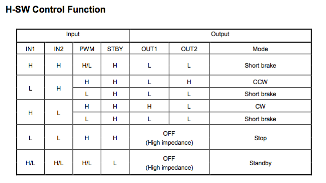
Logic Signals to Control Brushed DC Motors
Refer to the TB6612FNG Hookup Guide by Sparkfun, and the TB6612FNG datasheet.
Here is the logic control table from the datasheet: