Project Objective
Build a testing device to measure the deflection and twist of hydrodynamic fins under user specified loading distributions.
Team
"The team photo will be taken and imported at a later date"
The AFTTR Hours Gang consists of:
Background
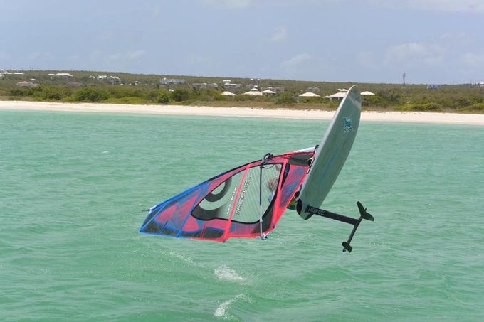
The project sponsor, Kean “Roo” Rogers, has been chasing windsurfing speed records for over 30 years. Current windsurfing designs have hit a wall in terms of achievable speeds though. The current windsurfing world record stands at 53.27 knots (61 mph), while the wind powered watercraft record is 65.45 knots (75 mph), set by Veritas Sailrocket 2. Windsurfers have a large planing surface which creates large amounts of drag to overcome, whereas Sailrocket uses hydrofoils to greatly reduce drag. Windsurfers have begun to use hydrofoils in the hope of increasing their speeds, but have run into several problems.
The main problem that windsurfing hydrofoils are facing is controllability. When riders get into higher speed ranges, the drag quickly drops off while the lift remains constant. This sudden decrease in drag causes the hydrofoil to accelerate, increasing the lift produced. The lift increases so suddenly that the rider has no time to react, is unable to control the rig, and is thrown free. Current hydrofoils are very stiff, which means this transition and loss of drag happens very quickly. Several windsurfing experts theorize that creating a more flexible fin will make the transition to higher speed ranges more gradual and controllable, thus allowing riders to fully utilize the low drag capabilities of the hydrofoil and achieve higher speeds than ever before.
Customer Requirements
In order to build more flexible fins, the sponsor requires a testing rig that can quantitatively measure the stiffness of hydrodynamic fins. The high level list of requirements is as follows:
- The device is to accommodate any fin shape and size between 0.2 and 0.5 meters long.
- The device is to apply loads in an automated fashion.
- The device is to approximate user defined loading conditions.
- The device is to record the deformed shape of the fin.
- The device is to save and export test data.
The test rig must be able to accommodate a variety of fin shapes and sizes, including straight, swept, and delta, in addition to any foil cross section, between 0.2 and 0.5 meters long. The device must also apply static loads to the fin to mimic real world loading conditions. Additionally, user must be able to modify the magnitude and shape of the loading distribution applied to the fin. Finally, the device must record the shape of the fin before and after the loading is applied and export this data in an easily readable format.
Design Challenges
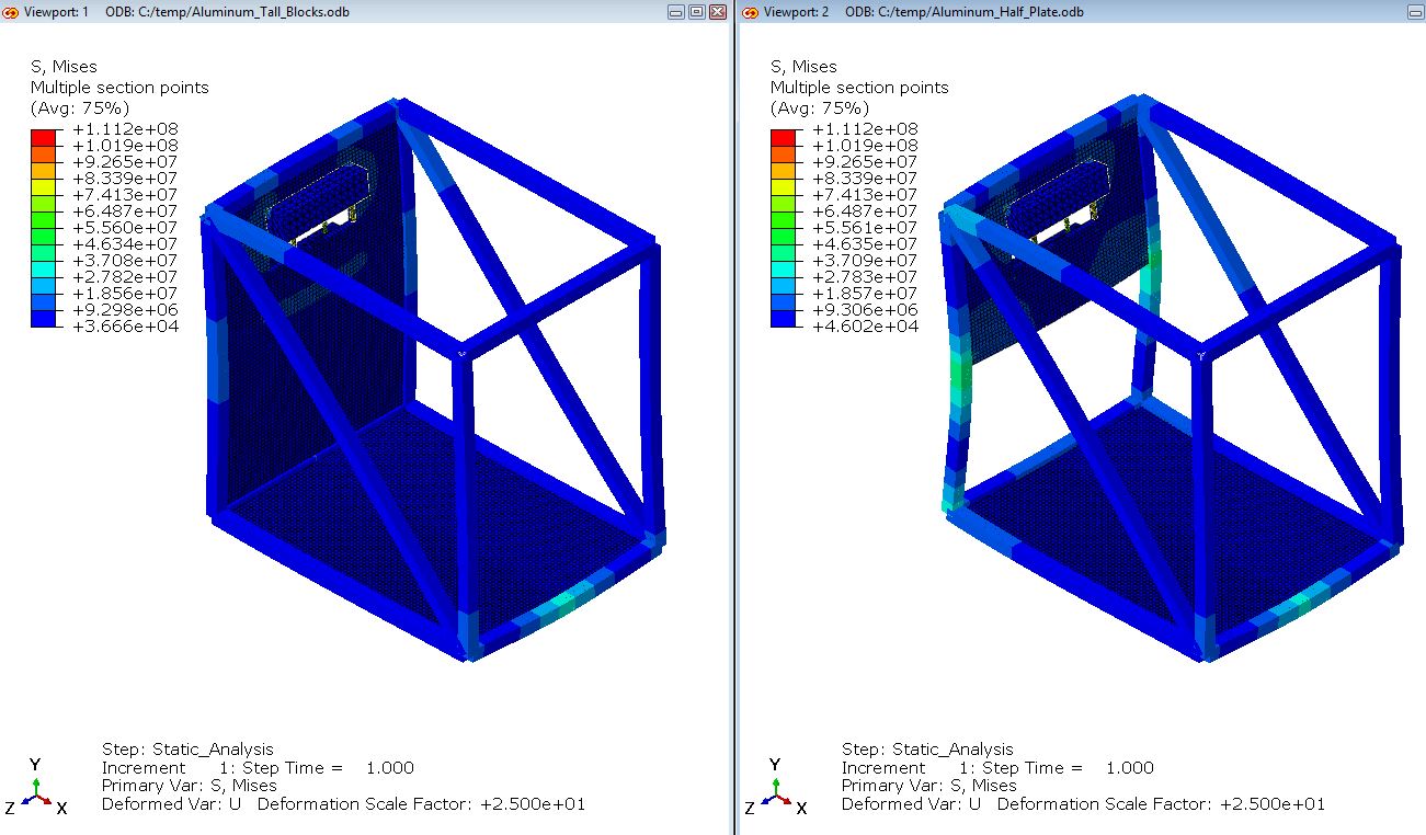
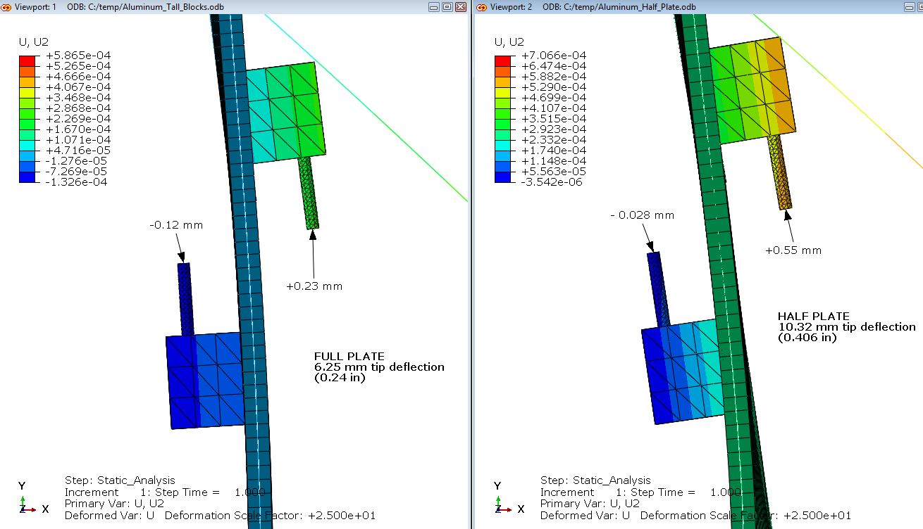
The AFTTR Hours Gang came up against several design challenges, which we have overcome to produce a robust design which meets all of the customer requirements. One major challenge was creating a frame stiff enough to withstand the load applied to the fins while not deflecting appreciably and affecting the results of the test. The team developed a triangulated load frame which was analyzed using Finite Element Analysis (FEA) techniques to ensure it met the design requirements (Figures 3 and 4).
Another major challenge was designing a measurement system accurate enough to precisely measure the deflection of the fins. The initial near-infrared laser time-of-flight sensor did not meet the accuracy requirements of +/- 1 mm, so the team instead devised a system which used a pair of digital calipers to provide the necessary measurements.
Outcomes
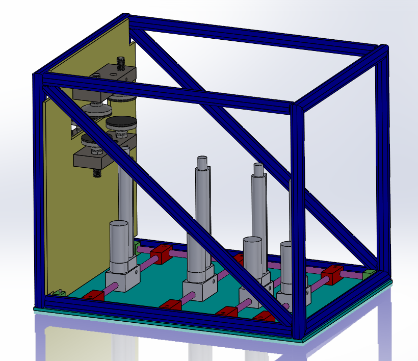
As of April 25, 2018, the AFTTR Hours Gang has finished approximately 75% of the project. We finalized the design for frame and load application systems, and have built all of the mechanical components for them. We are currently designing the measurement system and writing the control code for the device. New ideas are continuously being tested and improved during the design process. The team is making good progress and will be able to provide a complete, tested, and functioning device by June 7, 2018. The current model of the AFTTR is shown in Figure 5.