Project Objective
Design and test a robust automated mechanical device utilizing existing software to aid drowning people regardless of age or ability, to be delivered by Q2 2017 with a prototyping budget of $800.
Team
The project team is:
-
Sam Mohler

Customer/Market Requirements
Intel is looking for a robotic and/or automated solution to provide, at a minimum, floatation assistance for a person in distress, and up to full automated rescue of a submerged person. This device will be activated by a third party, and will have approximately 10 seconds to reach the person in distress; depending on the features of the device. The device shall be designed around use in and around a home or public pool, though other future location opportunities should be considered.
Design Challenges
The design team is developing multiple subsystems to approach the problem. Each subsystem was chosen to address specific customer requirements as well as concerns raised during the design process. The primary challenge faced to date has been identifying a problem area in the concept stage and tailoring a subsystem to address the issue.The compounding challenge in subsystem development was determining how to properly develop the subsystems into a cohesive unit to deliver a fulling functioning prototype.
- Hydrodynamic device for flotation delivery:
- Device must be unpowered.
- Device must house all other components.
- Device must be able to consistently follow the same trajectory.
- Inflatable flotation device:
- Flotation must occupy minimal space when not in use.
- Flotation device needs to be sufficiently large when deployed to aid 95% of the population.
- Flotation must transition from packed to deployed in less than 10 seconds.
- Flotation needs to deploy when under the drowning victim.
- Logic system to actuate the flotation device:
- Logic system must be completely submersible.
- The logic system must incorporate a microcontroller, relay, sensors, logic battery, drive battery, inflation mechanism and deployment mechanism.
- The logic system must work in tandem with the flotation device and delivery device.
Outcomes
The design team is developing a scale design that which demonstrates how each subsystem interacts to deploy a flotation device under a drowning victim.
The starting point of the design was the testing of various rigid and nonrigid flotation devices to determine optimal geometries and gain a basic understanding of the geometries behaviors under water. Included below is the highlights video from the first round of testing.
Pool Test March 10, 2017
The conclusion drawn from testing was twofold. First, in order for the flotation to rise vertically through the water, it needs to be as rigid as possible. This is best demonstrated by the Jim Buoy in the video. Use of a non-elastic inflatable device allows for this rigid behavior. PEVA (polyethylene vinyl acetate) was sourced as the material that best met this requirement as its elasticity is relatively low while also having a high level of heat weldability which is required for fabrication. Secondly, the Toypedos in the video demonstrated that it will be possible to create a unpowered delivery system which is highly accurate.
Pool Test May 5, 2017
Pool Test May 19, 2017
Flotation Subsystem:
As flotation was the primary requirement of this project, careful consideration had to be paid to materials, and geometries, to determine which combination yielded the best results. Two prototype flotation devices were constructed using both PEVA and vinyl materials in order to determine which offered the best performance. Ultimately the vinyl performed best as it was easiest to manufacture, and had superior strength when compared to the PEVA. The weld of choice for vinyl was chemical using a vinyl cement. The heat welds weakened both materials, resulting in ruptures at the edge of the weld, particularly with the PEVA material. During the process of heat welding, the welded material became more brittle, losing much of its elasticity. During testing, the PEVA flotation ruptured when inflated.
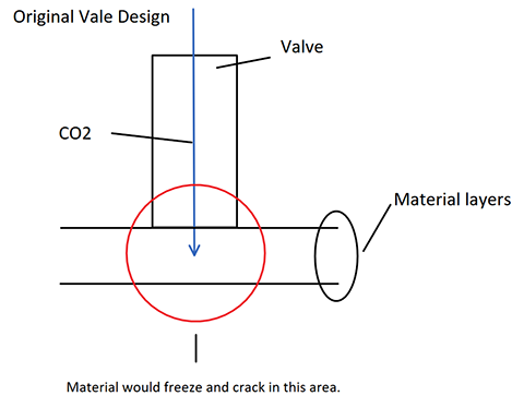
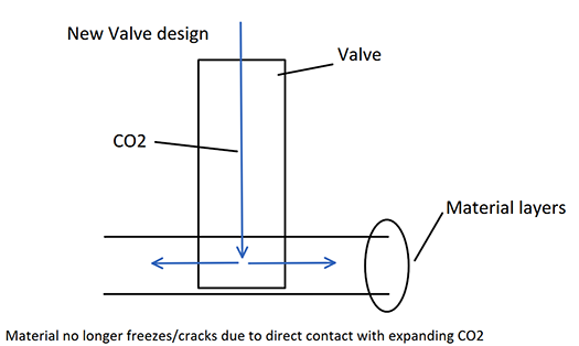
The vinyl proved to be much stronger when chemically welded as it held the pressure without rupturing. Heat welds proved to be stronger with the vinyl as well, however the material still ruptured on more than one occasion. Both materials became very brittle when the CO2 came in contact with them during inflation, and both ruptured due to this. A valve was constructed that protruded into the flotation to direct airflow into the flotation parallel to the material, as opposed to perpendicular to the material, while maintaining a large enough gap to keep the material from freezing. Pictured below are rudimentary diagrams of the original and new valve designs.
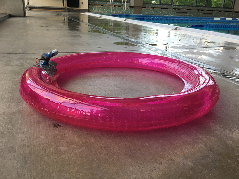
The valve used in testing is the same basic system that will be used in the logic subsystem. However, for this part of the experiment, it remained manually operated. The valve system is expanded on in the logic section. Pictured below is the prototype vinyl flotation with the manual valve seen on the left side.
Logic Subsystem:
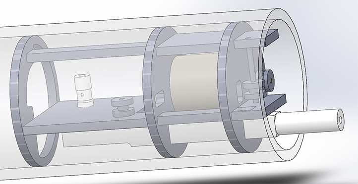
The logic subsystem is an area of the prototype that has morphed from a simple microcontroller to a complex electric and mechanical system based on the demands of other subsystems. Due to the size limitations imposed by the delivery system, the power and air supply requirements of the flotation system, and the availability of materials, the logic enclosure now contains a high power electric motor and power supply, an inflator valve and CO~2~ cartridge, microcontroller and relay, pressure sensor, and facilities for charging and communication outside of the 3 inch diameter enclosure.
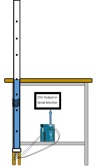
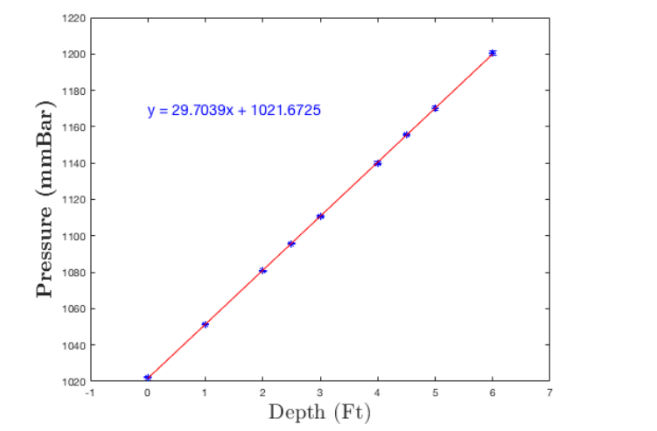
A key component of the prototype is the ability to accurately and repeatedly detect current water depth. After researching what is available, the high accuracy MS5803-05BA waterproof altimeter was assembled and evaluated using the test apparatus as shown below in Figure 3. Figure 4 shows the output from this sensor. In testing, the altimeter module demonstrated the ability to consistently resolve the depth of immersion to approximately 1 inch.
Ejection Subsystem:
The ejection subsystem quickly became one of the key design considerations for the team as the project transitioned from blue sky to concrete drawings, testing and manufacturing. Early considerations focused on buoyancy and communication between the flotation and logic subsystems. How exactly the flotation subsystem emerges from the main (body) of the device after the it reaches the desired target became a concern once the team discovered that a quickly expanding vinyl inflatable within a pipe would become lodged and otherwise deformed upon activation unless properly ejected or allowed to expand. The team came to two conclusions regarding how to deal with this issue:
- Allow the inflatable to expand by designing the back end of the pipe to flower open
- Eject the inflatable from the back end of the pipe using a powerful spring
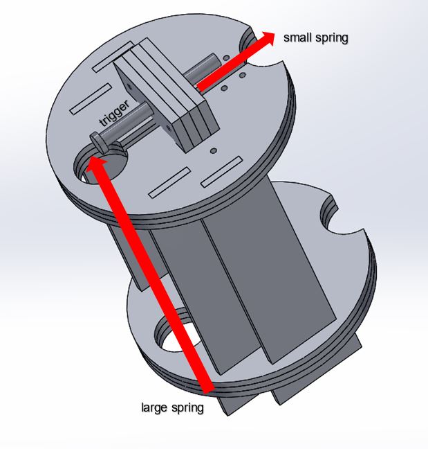
After some deliberation, the team decided to pursue the second option and design a device to physically jettison the flotation out of the pipe under the drowning victim. This approach allows the flotation to expand freely without the constraints of a flowering tube and facilitates waterproofing, manufacturing and reloading of the device. The preliminary designs of the ejection subsystem involved a large spring with a spring force or approximately 1.4 lb/in. Which was held in place by a trigger that was in turn actuated by a servo. A prototype was constructed and several motors tested, but the force required to overcome the frictional force and torque generated by the ejection spring proved too much for the servos available to our team. Various mechanical advantages were employed including a lever, but the servos all failed to actuate the ejection mechanism. To overcome the weakness of the servos, the previous approach was abandoned entirely and a new housing was developed utilizing a second, smaller spring to actuate the trigger and release the larger spring. The smaller spring is held in compression by two thin steel wires that are broken by way of an applied electrical current. Once the wires are broken, the compressed smaller spring pulls back the trigger and releases the larger spring, effectively ejecting the flotation device beyond the mouth of the pipe.
Further considerations for the ejection subsystem include waterproofing, repeatability and ease of rearmament.