Project Objective
Design, build, and test a platform for testing control systems for balance of a bipedal robot by June 1, 2017 with a budget of $1800.
Team
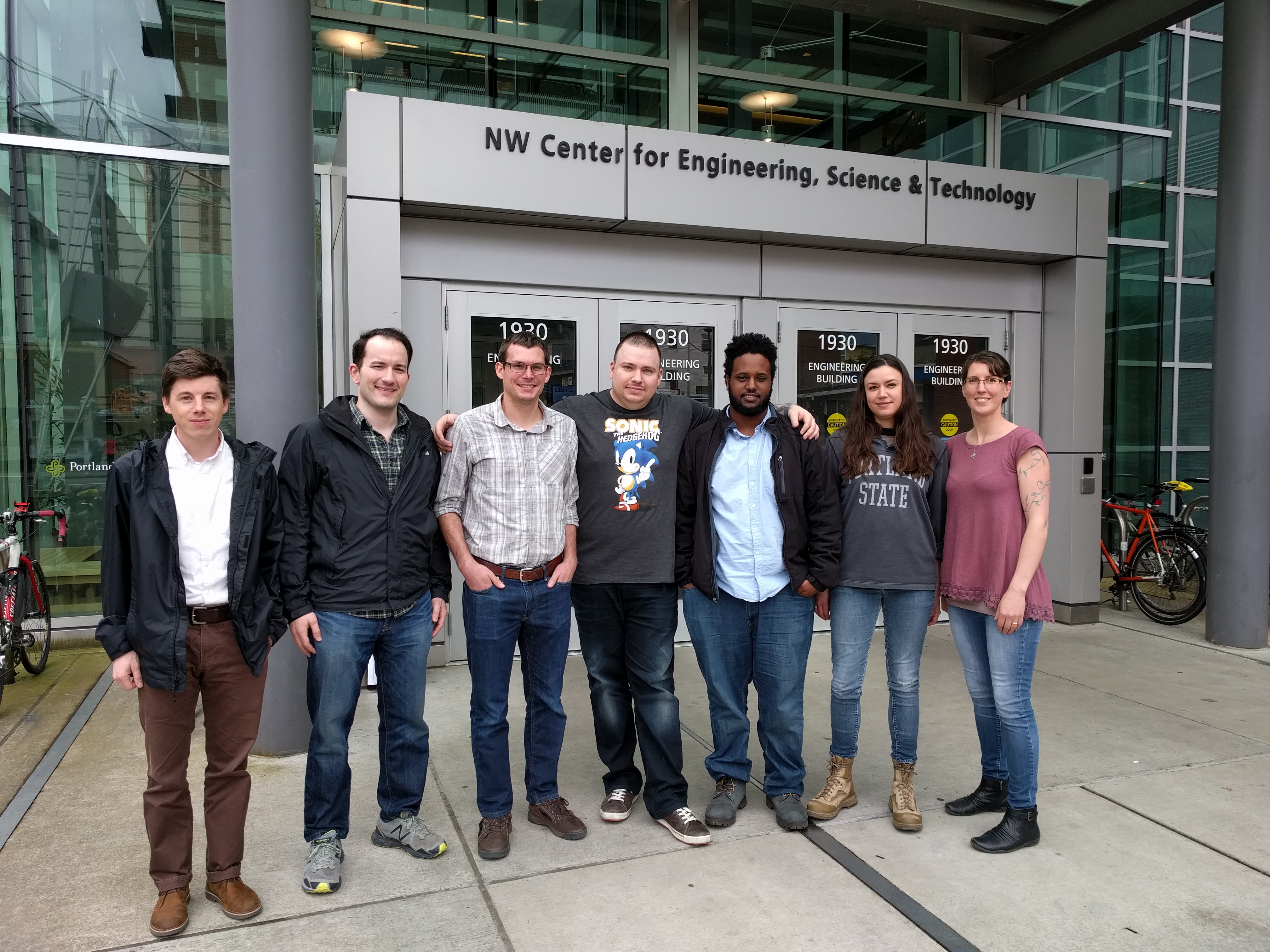
The project team is
- Eric Bryant
- Matthew Kennedy
- Ezana Mulugeta
- Lisa Reynolds
- Tiffany Stager
- Alexander Steele
Customer/Market Requirements
The focus of this project is to build a platform that enables the study and testing of control systems for the balance of a bipedal robot.The project sponsor requires a platform that allows for user prescribed motion in 3 degrees of freedom (DOF). The platform must support a 20 lb robot and provide the following dynamic capabilities:
-
Linear acceleration up to 5 m/s2 with a maximum velocity of 1.5 m/s for a displacement up to 0.15 m.
-
Angular and oscillatory motion in two rotational DOF with a maximum displacement of 7.5 degrees at a maximum angular velocity of 50 degrees/s.
The platform must be accompanied by a user interface that enables inputs of direction, type, speed, and duration of motion. System dynamics data must be stored and accessible to the user.
Design Challenges
The team focused on a design which would provide the desired dynamic capabilities within the given budget. Although there are commercially available solutions, such as linear actuators, that would provide the desired dynamics, these solutions were found to be very expensive.
Consideration of an in-house built linear actuator, with meticulous design calculations, revealed severe limitations due to budgetary concerns. A four-bar linkage system was identified and modeled that provided the desired dynamics within budget.
Outcomes
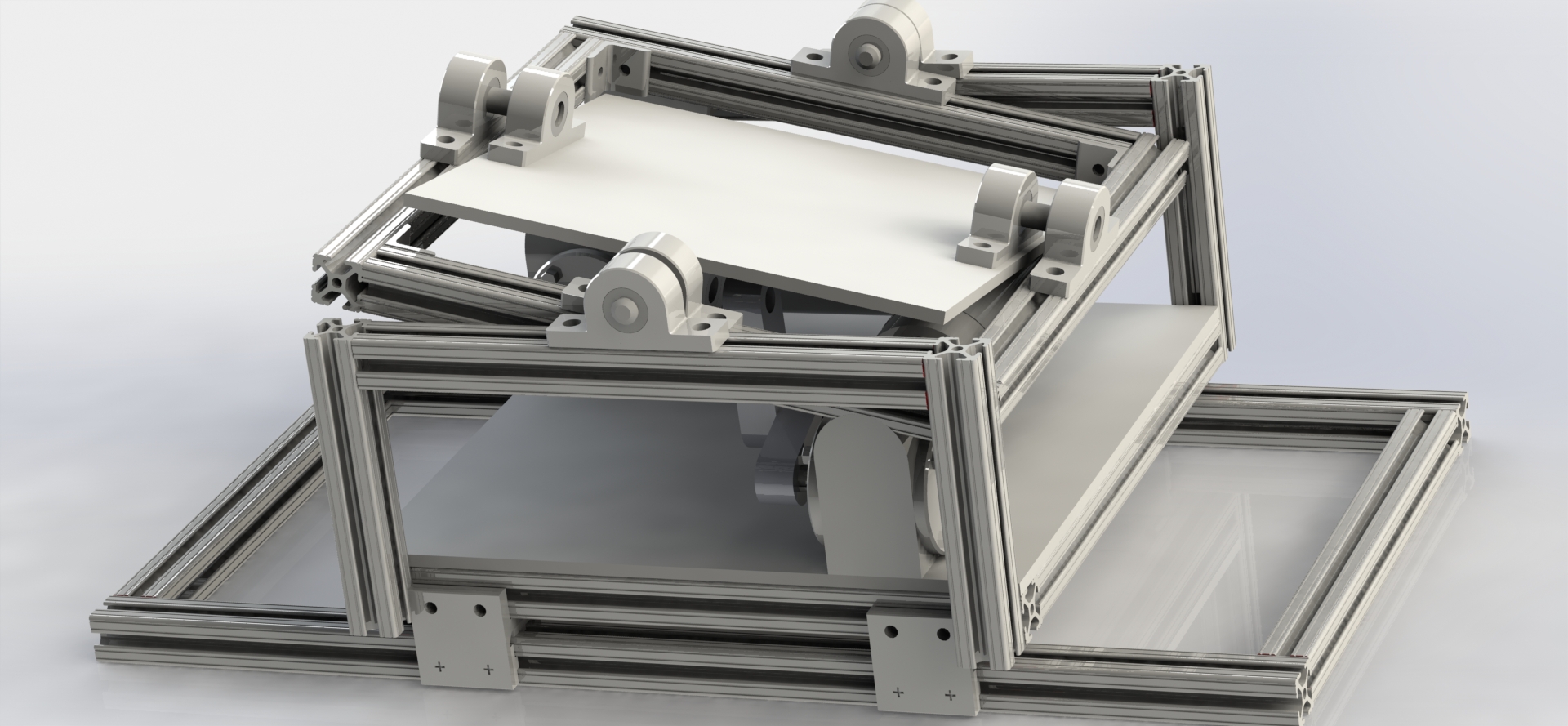
The team broke down the conceptual design into four components: an angular motion module, a linear motion module, a user interface, and real time control. Team members separately generated initial design solutions and each idea was given serious consideration until enough reasonable evidence was identified to deem an idea infeasible or failing to meet customer requirements. Via this design process and engineering analysis, the team chose a concentric ring design.
In the concentric ring design, the platform is suspended in a frame connected horizontally by bearings providing one angular degree of freedom. This frame is embedded in a second frame by bearings perpendicular to the alignment of the inner bearings. Key features include reduced vibration due to the use of bearings as linkages, reduced load on motors as the load is supported by the frame, and a simple dynamic model. The team concluded that this design is implementable, within budget, and provides the most robust design solution for angular movement of the platform.