Welcome to the PSU 3DSystems Capstone team page. In order to complete the requirements for Bachelor of Science in Mechanical Engineering, we are working with 3DSystems to improve upon a process for 3D printed injection molds.
Project Objective
The objective of this project is to develop process guidelines for rapid prototyping of injection molds, and to create a fixture for testing so that the customer (3DSystems) may be able to readily market the process in their catalog of products.
Team
The project team is
 |
 |
|||
| Azis Alnassar | MacGregor "Stu" Allison | Ryan Catabay | ||
 |
 |
 |
||
| Moira Gion | Serge Pakhyuk | Justin Rettger |
Customer/Market Requirements
- Fixture can directly test various mold designs for both mold and injection materials development.
- Mold must fit with the geometry of the existing Master Unit Die (MUD).
- Document fixture design and measurement system for evaluating mold designs.
- MUD must have connections for cooling lines.
Design Challenges
MATERIALS TESTING
The material being used to print molds is a propriety material developed by 3D Systems that will be called "X" from here on. X has a relatively low yield strength (6.98 kpsi—see "Special Formula" in Table 1), but a high ultimate strength. During the injection mold process, a pressure between 5 and 20 kpsi needs be applied between the two halves of the mold in order to ensure a proper seal. The X material is ductile enough to withstand these sealing pressures. However, under some circumstances, the pressures induced from the flowing plastic have been shown to weaken and destroy the mold over time.
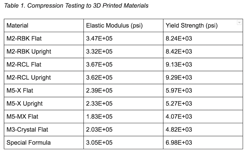
Comparing the samples of the X material and the material with the highest yield strength (M2_RCL), we see some key functional differences between the two materials. The X material test sample (Figure 1, left) stands beside an untested sample (right). There is clear plastic deformation, but no catastrophic failure in the part.
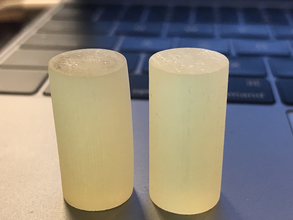
The M2-RCL sample (Figure 2) cracked and chipped under similar loading, which for the purposes of our application is a catastrophic failure.
TEST SHOOTS
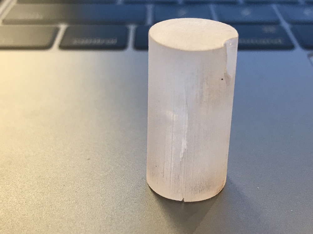
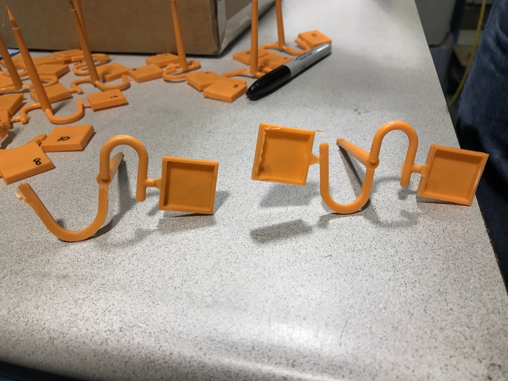
The first injection mold shoot tested shooting two simple square caps. One was fed by a trapezoidal runner and the other a circular runner. The trapezoidal runner created a stress concentration at the gate and caused a failure of the mold (Figure 3). Circular runners will be used for future tests.
As the mold is shot more times, the quality of the part begins to degrade. Figure 4 shows the first sample shot on the left and the sixteenth sample on the right. As the mold degrades, it produces parts with more flashing as the seal between the two halves of the mold begins to fail.
The following must be considered in order to optimize part properties and durability of the printed molds.
- Runner geometry (dimensions and shape)
- Gate geometry (sharpness of taper)
- Stress concentrations in cavities
- Provide an escape line for trapped gas to eliminate air bubbles
Outcomes
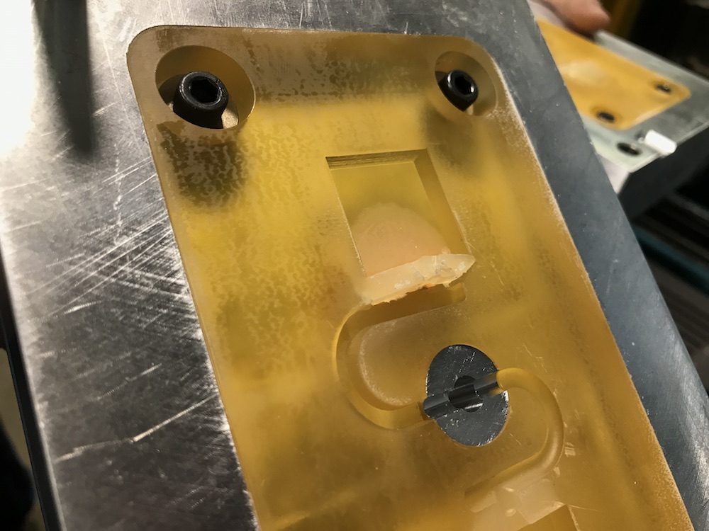
The next phase (Phase 2B) will utilize the same MUD that can be seen in Figure 3, but with a different printed mold. We will test shoot more complex geometries and measure those parts to learn more about how the mold degrades over time and what design changes we can implement to improve the life and performance of the mold.
Update
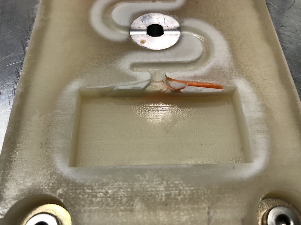
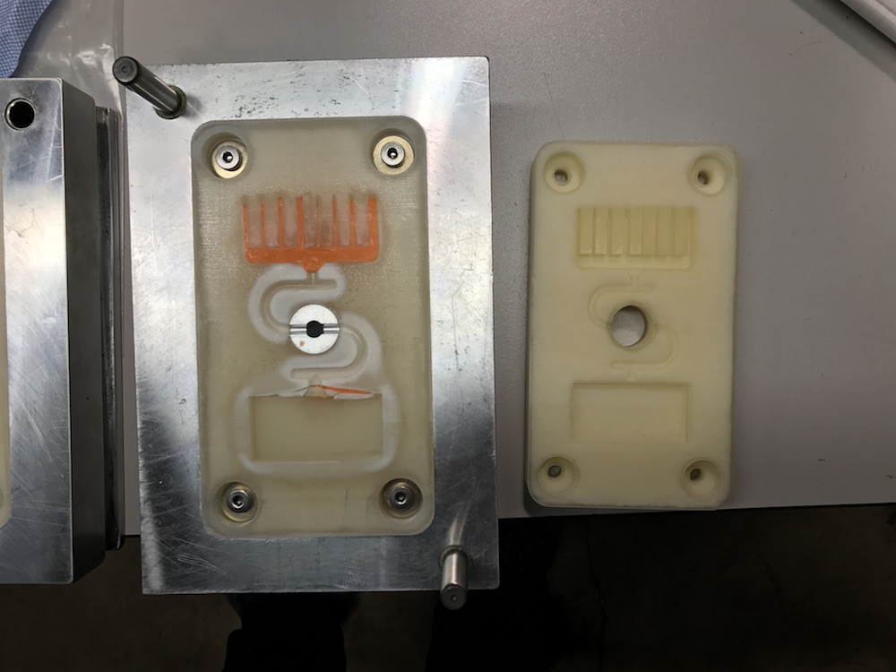
During Phase 2B shooting, the mold suffered a catastrophic failure (see Figure 5) early into testing because the draft on the part was not large enough. Figure 6 shows the tested mold next to an untested one.
Phase 2C shoot on 24 May 2017 will correct these issues.
In Phase 3 we will design and machine a larger MUD for the purposed of injection molding larger parts to test the limits of our process.