|
|
Our ECE 271 Project |
|
|
|
||
|
|
Our ECE 271 Project |
|
|
|
||
|
Links to the various parts of our project (in the order we completed them):
Other related links:
|
|
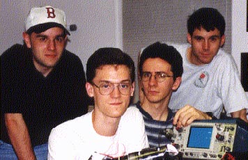
Team Members
Project Objective |
|
|
Our system will perform the following operations: • When an object is placed between the claws, the claws will automatically clamp down onto the object • When an object is removed from the claws, the claws will automatically open up to the full open position • If an object is placed within the claws grasp then removed two times in a row, the robot claw will not respond afterwards until the pressure sensor is "tripped" At the present time, we are only going to design a system which can perform the above functionalities. When we finish, and if we have time left over, we will expand the functionality of our system. Input/Output Definitions We will be using a Robotic Arm Trainer, Model: OWI-007. It contains a total of five motors within the robot for five different forms of movement, however; we will only be using the claw motor. Our system will utilize three inputs (X1,X2, and X3) and two outputs (Z1 and Z2). The inputs will come from sensors (actually switches) attached at various places on the robot claw. They will detect three different occurences: X1 will detect whether the claw is fully open (X1 = 0, claw not fully open; X2 = 1, claw fully open). X2 will detect whether an object has been detected between the claws (X2 = 0, object not detected; X2 = 1, object detected). X3 will detect pressure on the claws (X3 = 0, no pressure detected; X3 = 1, pressure detected). Because we are using a CMOS PLD, the switches must have pull-up resistors connected to them. This will prevent any accumulation of excess charge inside the PLD. Excess charge can possibly damage the internal fuses of the PLD. The two outputs will dictate the movement of the motor: Z1Z2 = 00 when the motor is stopped, Z1Z2 = 01 when the motor is clamping the claws down, Z1Z2 = 10 when the motor causes the claws to open up. The outputs will interface with two pair of relays which, in turn, will connect up to the robot claw motor. This will allow more current to flow to the motor than would be possible if the PLD output was directly connected to the motor. Project Design Procedure The following steps were taken during our design phase: 1). Formulated state diagram In this phase, we constructed a state diagram of our system using our predefined action/responses we wanted our system to have. These responses can be found in the Project Objective section of this page. See state diagram hyperlink. 2). Created .VHD file in VHDL After creating the state diagram, we created the .VHD file of our system. The .VHD file is similar to the .CPP file in C++. The VHDL file is essentially a programmed version of our state diagram. See controller.vhd hyperlink. 3). Compiled .VHD file (creates .JED file) and simulated circuit in NOVA. After creating the .VHD file, we then compiled it and used the resulting .JED file in the NOVA simulator. NOVA allowed us to put whatever inputs we wanted into the system. Once we agreed that the simulation matched our desired functionality, we determined that the simulation was correct. See VHDL simulation hyperlink. 4). Created controller.rpt. This results from the compilation of the .VHD file. The .RPT gives the pin layout of the PLD, as well as other information relating to the system. See controller.rpt hyperlink. 5). Assembled clock mechanism. We created a clock that operates at 77 Hz using a 555 timer, one capacitor and several resistors. Our design was taken from Doug Halls' book. See clock hyperlink 6). Programmed PLD and tested it on the oscilloscope. Using the .JED file we created after compiling the .VHD file, we programmed the PLD on the PLD programmer. Using our clock and some additional components (resistors, switches, power supply, etc.), we tested the logical operation of the PLD on the oscilloscope. 7). Assembled input interface. In this phase, we attached the three switches we will be using as sensors onto the robot claw. Because we are using a CMOS PLD, we had to assemble the switches with pull-up resistors so as to make the input on the PLD either a high (5V) or ground (0V). See sensor interface to PLD inputs hyperlink. 8). Assembled output interface. In this phase, we created the output interface that connects the PLD output to the claw motor. It consists of several transistors and four relays. We needed to create an output interface because the PLD output can not provide enough current by itself to drive the claw motor. See PLD interface to claw motor hyperlink. 9). Assembled complete system from subsystems. At this time, we can build our system, including input and output interfaces, clock, PLD and robot claw. This step also involves minor details, such as connecting the power to the various inputs, wiring subsystems together, etc. See block diagram of our system hyperlink. Final Thoughts This project was a fun exercise in discipline and intellect. All of us enjoyed creating a system that could actually respond to exterior inputs. As a result of this project, we have learned valuable principles dealing with states and logic systems in general. As such, we are well prepared for whatever obstacles may arise in our next sequence of courses and for the engineering profession in general. |
|||
ARGHH! It's got me!
|
|
Updated Regularly Last Updated Aug. 12, 1999 |
|
|
|
||