Functional decomposition is a technique for dividing a larger task into smaller tasks. During decomposition, the team focuses on the inputs and outputs of each task and uses generic descriptions of the process achieved by the task. The decomposition process is usually applied recursively until the design team can readily envision ways of achieving each of the sub-tasks. Functional decomposition is also called functional analysis, top-down design, or logical decomposition.
Functional decomposition can be applied to many engineering tasks. For our purposes, i.e. in ME 491-493, we use functional decomposition as a tool in the conceptual design phase. During conceptual design, the team uses functional decomposition to explore solutions to a given problem without overly constraining the choices for implementing those solutions. That is consistent with the "conceptual" part of Concept Design. Implementation details are workout out in the Subsystem Engineering phase (to use the terminology of Mattson and Sorenson).
A functional decomposition for a design goal is linked to a specific design concept. One should not expect one-and-only-one functional decomposition for a given objective. Since the design team will need to choose among competing conceptual designs, the team should expect to develop more than one functional decomposition. For example, consider the task of making coffee. Different functional decompositions would be needed to describe the a drip coffee maker, an espresso machine, or a machine that dispenses coffee made from "instant" powdered coffee.
Also remember that design will require iteration and refinement as the team's knowledge improves as the design evolves. Therefore, initial attempts at functional decomposition will likely need to be revised or even discarded altogether. The goal is greater understanding, not checking a box in some recipe for the design process.
Sections
- The Basic Idea
- Separating Function from Implementation
- Example: Automated Pencil Sharpener – Version 1
- Flow of Material, Energy and Information
- Use Verb-Noun pairs to define functions
- Example: Automated Pencil Sharpener – Version 2
Further reading from textbooks
-
Christopher A. Mattson and Carl D. Sorenson, Fundamentals of Product Development, 5th ed., 2017, Self-published, p. 228–229, "Decomposition",
-
Kevin N. Otto and Kristin L. Wood, Product Design: Techniques in Reverse Engineering and New Product Development, 2001, Prentice-Hall, Chapter 5.
-
Karl T. Ulrich and Steven D. Eppinger, Product Design and Development, 5th ed., 2012, McGraw-Hill, pp 121–123
-
David G. Ullman, The Mechanical Design Process, 5th ed., 2016, McGraw-Hill, section 7.3
-
G. Pahl, W. Beitz, J. Feldhusen and K.-H. Gote, Engineering Design: A systematic approach, 3rd ed., 2007, Springer-Verlag, section 6.3
The Basic Idea
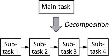
Functional decomposition involves breaking a larger task into subtasks. Figure 1 represents a single level of decomposition from a high level task into four subtasks. The number four is arbitrary and is only used here to demonstrate the idea.
The goal of functional decomposition is to transform a complex task into a sequence of smaller tasks that are easier to understand, and then easier to find practical ways of achieving. If the subtasks themselves are too complex, the subtasks are divided into sub-subtasks. Recursive subdivision of tasks is repeated until the smallest sub-tasks can be easily translated into practical details.

A functional decomposition diagram does not (usually) show multiple levels of decomposition on a single image. In other words, Figure 1 and Figure 2 are only meant to show how a high-level functional decomposition is refined. Your functional decomposition diagrams will be clearer if you show each level of refinement as a separate diagram. See, for example, Figure 3 and Figure 5, below.
Separating Function from Implementation
Functional decomposition can be used in many engineering tasks, from conceptual design of a device to optimization of manufacturing workflow. Functional decomposition can be used at any stage in a design, but it is very valuable early in the design process when the conceptual design is fluid or poorly understood.
A functional decomposition describes a design concept, but it does not specify how each of the subtasks are implemented. The focus is on discrete tasks and the organization of those tasks to achieve a goal. The decomposition also reveals the flow of material, information and energy necessary to carry out the tasks.
When decomposing and specifying subtasks, it is important to use generic functions for each task and sub-task. Avoid specifying how to implement the function for each function block. Later, after a draft of the functional decomposition is complete, ideas are generated for ways to implement (or achieve) each function. In this way, the functional decomposition becomes a starting point for developing implementation concepts.
For example, consider the task of designing a device to sharpen pencils. In a functional decomposition, the act of sharpening involves removing the wooden material surrounding the graphite. The sharpening task is specified as "remove material", not "grind wood". Describing the task as "remove material" allows alternative methods such as grinding, cutting or sanding, which may, depending on the use case for the pencil sharpener, be better solutions.
As the practical implementation details for each subtask are considered, the functional decomposition will evolve. Therefore, it is important to maintain a flexible attitude and iterate on the the decomposition. Also, although the decomposition should use generic function blocks, one should not be rigid or dogmatic about avoiding any thought of implementation details. Functional decomposition is just a tool to help organize your thinking during the conceptual design phase. The goal of keeping the decomposition separate from implementation details is to enable creativity in developing high quality design concepts. Implementation details can and should inform the functional decomposition, and vice versa.
Example: Automated Pencil Sharpener – Version 1
Let's continuing thinking about task of sharpening pencils. To be more specific, assume that the high-level task is to design a machine to automatically sharpen pencils. Suppose that the pencils are produced by an upstream manufacturing process that continuously fills a hopper of unsharpened pencils. The machine to be designed should remove pencils from the hopper and sharpen them one at at time.
Figure 3 is a high-level functional decomposition of the automated pencil sharpening machine. Remember that more than one functional decomposition is possible, and that each different functional decomposition corresponds to a different conceptual design. A more detailed decomposition is presented below.

Flow of Material, Energy and Information
For mechanical systems and devices, design experts recommend identifying the separate flows of material, energy and information in a functional decomposition. The material flow refers to physical objects (e.g. pencils) that are acted upon, or substances (e.g. fluids) that move through the system to perform a function. The information flow involves the control system, sensors, and signals from sensors and to actuators. The energy flow is related to the power necessary to perform operations. The energy can be electrical, mechanical (force, torque), or human (lifting, turning valves).
Figure 4 represents the flow of information, material and energy into and out of a function. To make these flows clear, each is represented with a different color and line type.

Use Verb-Noun pairs to define functions
In describing functions, use a Verb-Noun pairs. The verb describes the function applied to the noun.
Examples:
remove material
locate fastener
heat cylinder
Example: Automated Pencil Sharpener – Version 2
To illustrate the use of material, energy and information flows, the "Remove material" task from Figure 3 is decomposed into more detail in Figure 5. The level of detail exposes the interactions between the control system, the energy supply, and the device that performs the sharpening.

Note that no details of the sharpening device are provided in Figure 5. Therefore, further decomposition is needed. Also note that the use of the control system to turn power on and off to the sharpening device is just one choice. An alternative design would keep the sharpening device powered-on at all times, which would require another sub-system to mechanically engage and disengage the pencil from the sharpening device. The level of detail in Figure 5 makes these additional design choices more obvious, which is an advantage of performing the functional decomposition in the first place.