Overview of Plumbing for the Salinity Sensor Loop
This web page gives an overview finished assembly of the plumbing for the salinity sensor flow loop. Instructions for assembly of the sensor loop plumping are divided into the following steps.
Return to the main page for the assembly of the salinity loop plumbing.
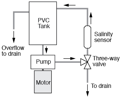
Schematic
As indicated in the following schematic, the pump recirculates water from the PVC tank through the salinity sensor. A three-way valve allows the system to be drained without disconnecting any plumbing.
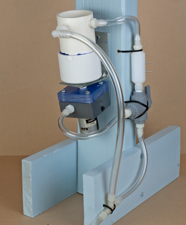
Finished flow loop assembly
The final version of the salinity sensor flow loop is shown in the following photograph. The two drain lines are joined by a tee fitting visible in the bottom of the photograph.
On to the details ...
Now that you see the final product, we'll build this system in two steps. First, mount the pump and the fish tank.