Motion sensor on the CPX
Table of contents
- Motion Sensor
- Demonstrations of Motion Sensor Readings
- Using the Accelerometer to Indicate Orientation
Motion Sensor
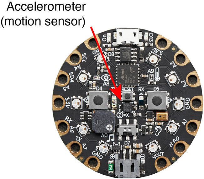
The Circuit Playground Express has an LIS3DH accelerometer mounted between the two large buttons and just below the Reset button. In the Circuit Playground documentation, the accelerometer is referred to as a motion sensor.
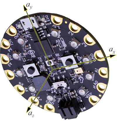
The motion sensor detects acceleration in three orthogonal axes, \(x\), \(y\) and \(z\). The stencil on the surface of the CPX indicates that \(x\) and \(y\) components of acceleration are in the plane of the board, and \(z\) is (by the right hand rule) pointed up from the surface. The following image shows the \(a_x\), \(a_y\) and \(a_z\) axes as an orthogonal triad of vectors emanating from the body of the accelerometer. The motion sensor independently measures the acceleration in each of those coordinate directions.
Demonstrations of Motion Sensor Readings
The Hello_Accelerometer sketch is part of the Adafruit Circuit Playground library. Open the sketch by selecting File –> Examples –> Adafruit Circuit Playground –> Hello_CircuitPlayground –> Hello_Accelerometer in the Arduino IDE. Running the sketch produces three readings, one for each acceleration component, that are sent to the Serial Monitor.
Instantaneous Plot of Accelerometer Readings with demo_accelerometer.ino
The demo_accelerometer.ino sketch is a slight modification of the Hello_Acceleromter.ino sketch from the Adafruit library. The demo_accelerometer.ino sketch sends only numerical values, no text, to the Serial object, which makes that output viewable with the Serial Plotter.
Download demo_accelerometer.ino. After uploading the demo_accelerometer.ino sketch to your Circuit Playground, you can open the Serial Plotter (in the Arduino IDE) to view the instantaneous values of \(a_x\), \(a_y\), \(a_z\) and the magnitude of the acceleration \(a_\mathrm{tot}\).
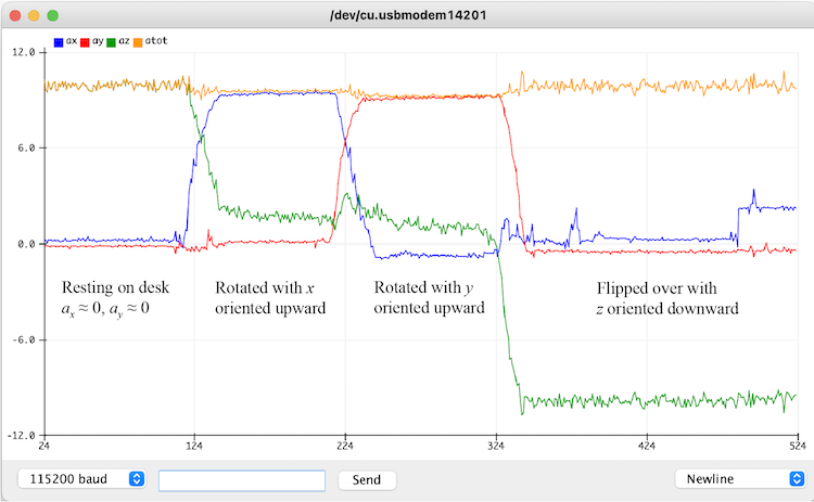
The following image is an example of the Serial Plotter window when the demo_accelerometer.ino sketch is running. The annotations, which do not appear in the Serial Plotter window, indicate the orientation of the Circuit Playground relative to the surface of a desk. Other than the transition between orientations, the Circuit Playground was mostly motionless, which means that the maximum accelerations are close to \(g = \pm 9.81\ \mathrm{m}/\mathrm{s}^2\).
Accelerometer Readings
In the demo_accelerometer.ino sketch, the three channels of the accelerometer are read with the following statements.
  float ax, ay, az, atot;

  ax = CircuitPlayground.motionX();
  ay = CircuitPlayground.motionY();
  az = CircuitPlayground.motionZ();
The values of ax, ay and az are the acceleration components in the \(x\), \(y\) and \(z\) directions, respectively, in units of \(\mathrm{m}/\mathrm{s}^2\).
Acceleration is a vector quantity. The magnitude of the acceleration vector is computed with
atot = sqrt( ax*ax + ay*ay + az*az );
The expression ax*ax is used instead of pow(ax,2) because multiplication is faster in this instance. Note that the C language does not have an exponentiation operator, like ^ that is available in other languages.
Board at Rest
When the board is at rest, regardless of the orientation, the total acceleration should be close to the acceleration of gravity, \(9.81\ \mathrm{m}/\mathrm{s}^2\). As shown in the image of the Serial Plotter window, above, or in the values exported to the Serial Monitor, the maximum output of the accelerometer is not equal to \(9.81\ \mathrm{m}/\mathrm{s}^2\). That is not surprising since the sensor is very low cost and is not designed for precise acceleration measurements. According to the LIS3DH datasheet, the zero-offset accuracy of the accelerometer is \(\pm 40\)g or \(0.39\,\mathrm{m}/\mathrm{s}^2\) when operating on the \(\pm2\)g range.
Despite the modest accuracy of the sensor, the acceleration data is very useful for tasks such as detecting orientation or detecting sudden movement.
Using the Accelerometer to Indicate Orientation
When the accelerometer is stationary, or moving slowly, the output of the accelerometer can be used to indicate the orientation of the Circuit Playground with respect to gravity. Orientation data is useful in many applications such as a digital level that indicates whether a surface is horizontal or vertical, or in a game interface that uses tilt to steer a physical or virtual object. We present two simple examples that use the orientation of the Circuit Playground to turn NeoPixels on and off.
Basic Orientations
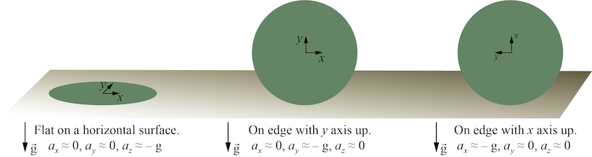
The following schematic shows a model of the Circuit Playground in three primary orientations, each with one of the axes of the accelerometer parallel to the gravity vector. By comparing the magnitude of \(a_x\), \(a_y\) and \(a_z\) to the acceleration of gravity, we can infer the orientation. For example, when the magnitude of \(a_z\) is close to negative \(g\), we infer that the Circuit Playground is resting on a horizontal surface with the face of the Circuit Playground oriented upward.
fliplight.ino Sketch
The fliplight.ino sketch demonstrates how the accelerometer reading can be used to control another action. In this case, all of the NeoPixels are turned on whenever the face of the Circuit Playground is oriented downward, i.e. whenever \(a_z<0\).
Download fliplight.ino. and experiment with different orientations.
fliplight_angle.ino Sketch
The fliplight_angle.ino sketch is a modification of the fliplight.ino sketch such that the NeoPixels are turned on only when the Circuit Playground has a limited range of downward tilts. Implementing this criterion requires a quick calculation using the geometry of vectors in three-dimensional space.
As shown in the following image, when the Circuit Playground is in an arbitrary orientation there is an angle \(\theta\) between the gravity vector and the \(a_z\) component measured by the accelerometer.
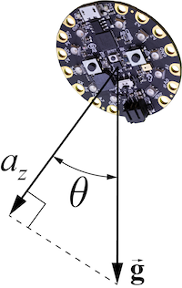
When the Circuit Playground is stationary (or moving very slowly), the \(a_z\) reading will be the component of the gravity vector projected onto the (local) \(z\) axis of the accelerometer. Using trigonometry in the plane shared by \(\vec{g}\) and the \(z\) axis we get
\[a_z = g \cos \theta\]Solving for \(\theta\) gives
\[\theta = \cos^{-1}\left( \frac{a_z}{g} \right)\]Also when the Circuit Playground is stationary (or moving slowly), the total acceleration measured by the accelerometer is equal to the acceleration of gravity. Thus, (when the Circuit Playground is stationary)
\[g = \sqrt{a_x^2 + a_y^2 + a_z^2}\]Substituting this expression for \(g\) into the formula for \(\theta\) gives
\[\theta = \cos^{-1}\left( \frac{a_z}{\sqrt{a_x^2 + a_y^2 + a_z^2}} \right)\]The preceding formula allows us to compute the angle between the \(z\) axis of the Circuit Playground and the gravity vector.
The fliplight_angle.ino sketch uses a criterion on the magnitude of \(\theta\) to determine when the NeoPixels are turned on. The following excerpt shows the key lines in the loop function of fliplight_angle.ino.
float delta_theta = 30.0;  //  difference in angle that determines whether NeoPixels are turned on

// -- Retrieve acceleration components and compute the total
ax = CircuitPlayground.motionX();
ay = CircuitPlayground.motionY();
az = CircuitPlayground.motionZ();
atot = sqrt(ax*ax + ay*ay + az*az);   //  could also use pow(ax,2), but ax*ax is faster

theta = (180.0/PI) * acos(az/atot);   //  180/PI converts radians to degrees

// -- Turn all NeoPixels on only when theta is within delta_theta of 180
if ( abs(180.0 - theta) < delta_theta )  {
  setAllNeoPixels(255,255,255);             //  All on, white
} else {
  setAllNeoPixels(0,0,0);                   //  All off
}
Download fliplight_angle.ino. and experiment with different orientations of the Circuit Playground and different values of delta_theta.