DC Fan
A small DC fan can be powered by passing electrical power through the VOUT and GND pins on the Circuit Playground Express.
Table of contents
- Continuous Power via VOUT and GND
- Prototype Wiring with Alligator Clip Leads
- On/Off control
- PWM Speed Control
Continuous Power via VOUT and GND
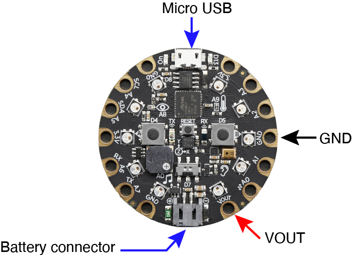
The digital I/O pins on the Circuit Playground Express cannot supply sufficient current to run a DC fan. Instead, we will use the VOUT pad on the Circuit Playground as the power supply for the small fan. The VOUT pad is connected to the positive voltage source from either by the USB connection or the battery. The fan in the kit of parts for the Invention Bootcamp is rated at 5VDC and 0.2A, which is within 0.5A limit on the USB 2.0 specification for a high power device.
The following image identifies the VOUT and GND pads that are used as the power source for the small DC fan.
Prototype Wiring with Alligator Clip Leads
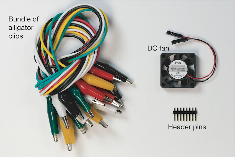
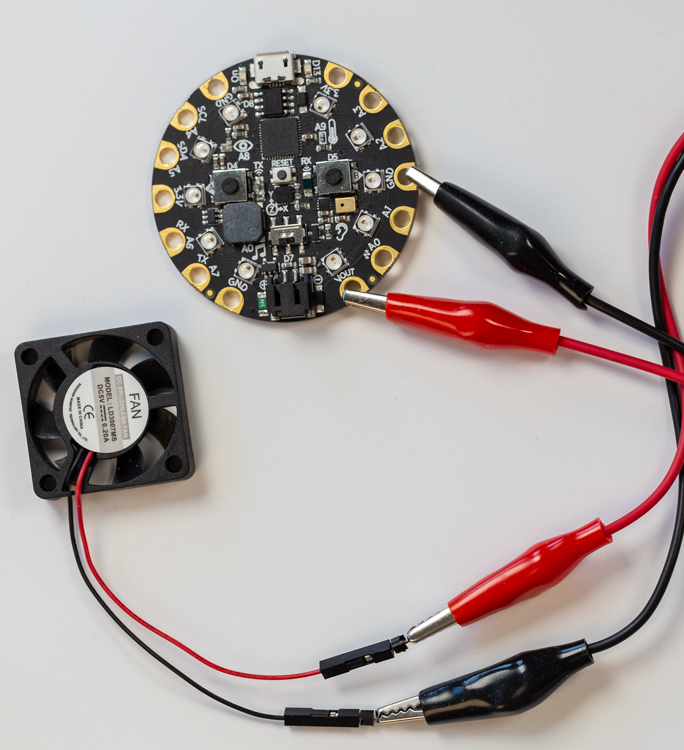
The small DC fan from the Invention Bootcamp kit can be connected to the Circuit Playground with alligator clips and some header pins. The following image shows the components.
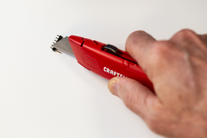
The header pins provide a way to connect the alligator clips to the socket ends of the power leads on the fan. We only need two of the pins. Use a knife or side cutters to separate two of the metal pins from the section of header.
Notice that the header has notches in the plastic that holds the section of pins together. Applying the cutting edge of a knife or a sidecutter (pliers) to the notch allows you to separate individual pins from the second of header. Be careful as the isolate pin may travel quickly and far when it is separated. We recommend that you use safety glasses when separating the pins.
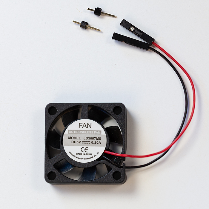
Once the two pins are separated from the section of pins, you can leave the plastic piece that may stay attached to the individual pins or you can remove the plastic by sliding it over the end of the metal pin .
Insert the long end of each pin into the socket for the read and black leads on the fan.
Use the red alligator clip to connect the pin protruding from the red lead of the fan to the VOUT pad on the Circuit Playground. Use the black alligator clip to connect the pin protruding from the black lead of the fan to the GND pin on the side of the Circuit Playground. The following image shows the connections.
After the fan is connected to the Circuit Playground, connect the Circuit Playground to a USB port or a USB style socket on a wall power supply. When the connections are made, the fan should spin rapidly.
On/Off control
An NPN transistor circuit can switch more current than the I/O pins of a microcontroller. The typical control circuit is shown below. The collector (C) and emitter (E) pins of an NPN transistor are connected to the fan ground and system ground respectively. A digital output pin is connected, via a fixed resistor, to the base (B) of the transistor.
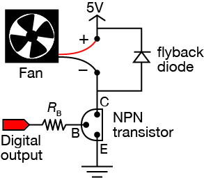
When the digital pin of the microcontroller is is set to HIGH, a small current flows from the microcontroller to the base and to ground (\(I_{BE}\)). The \(I_{BE}\) current energizes the transistor, which allows a larger current to flow from the collector to the ground. Thus, when the digital pin is set to HIGH, the transistor acts like a switch that is closed, allowing current to flow to ground. When the digital pin is set to LOW, the transistor acts like a switch that is open, preventing current flow.
We recommend a flyback diode across the fan supply voltage to dissipate power stored in the fan windings when the current flow to ground is interrupted, i.e. when the digital pin controlling the transistor is switched from HIGH to LOW. A general purpose diode such as a 1N4001 is sufficient.
PWM Speed Control
Pulse-width modulation (PWM) is commonly used to control speed of a brushed DC motor. The same transistor circuit used for on/off control applies. Instead of a simple on/off signal from the digital I/O pin, a PWM signal to transistor limits the power to the fan, which in turn controls its speed.