Visualization of Geologic and Contamination Data at the
East Multnomah County Groundwater Contamination Site
by
Technical Report EWR-2-98
Department of Civil Engineering
P. O. Box 751
Portland State University
Portland, Oregon 97207-0751
June 26, 1998
Prepared for Friends of Blue and Fairview Lake under support of the U.S. Environmental Protection Agency TAG Program
The Friends of Blue and Fairview Lake (FBFL), a citizen activist group, applied for and received an EPA Technical Assistance Grant (TAG) and contracted with Portland State University faculty and staff to serve as the Technical Advisor and provide a review of the issues related to contamination in East Multnomah County, Portland, Oregon. A description of this site and the remedial and study actions to date are noted at http://www.ce.pdx.edu/~scott/pubs/fairview.
The contents of this report are designed to satisfy the following agreed upon tasks:
It should be noted that this report is designed to be a snapshot of the current conditions involving the community's ground and surface water systems and the surrounding contamination areas. The intent is for this to be an educational tool for displaying the geology, hydrogeology, and contamination threats to the FBFL water systems. There is no attempt to form conclusions beyond the available data other than to outline possible scenarios that may be inferred from the present conditions. As more data become available and as the site is better understood through further study and observation, some of the observations and conclusions contained herein may change.
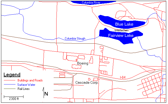
The groundwater contamination is located in the Cities of Fairview and Gresham in East Multnomah County, Oregon, which is in the eastern part of the Portland metropolitan area (Figure 1). The region of groundwater contamination can be found within a 2.5 square mile region bounded by NE Halsey Blvd. to the south and the Columbia River to the north. The study region is also bounded by NE 178th to the west and by NE 223rd Ave. to the east.
(Excerpted from PSU Technical Report EWR-5-97)
In 1963, the first manufacturing building was constructed by Electronic Specialty Company (ES Co.) a major subcontractor to The Boeing Company at the time. In 1969 the ES Co. was acquired by International Controls Corporation, which in turn transferred the Portland plant to a Boeing subsidiary, Radiation International, Inc. By 1979 Boeing was the sole owner of the facility property and improvements. In 1979 and 1980, Boeing constructed a wastewater pre-treatment plant, employee recreation areas, and building 85-105, used for parts assembly and storage.
From 1981 to 1984, Boeing utilized a surface impoundment for the temporary storage of rinseate from electroplating and metal finishing operations prior to transfer to the wastewater treatment plant. Upon closure of the impoundment in 1985, a Detection Monitoring Program was implemented as required by DEQ. Six groundwater-monitoring wells, installed around the perimeter of the impoundment, were monitored from January 1986 to July 1987. Contaminated groundwater was found with high levels of trichloroethylene (TCE), 1,1,1-trichloroethane (TCA), and methyl ethyl ketone (MEK). The monitoring program revealed that other point sources were suspected due to the elevated levels of contaminants detected in upgradient monitoring wells.
The Cascade facility was constructed from 1955 to 1956 for the purpose of manufacturing forklift truck attachments. At the time the facility included a waterfall paint booth, a parts assembly area, a maintenance shop, an assembly area for hydraulic cylinders, two underground storage tanks (USTs) for gasoline storage, and offices. In 1961, Cascade installed a vapor degreaser near the hydraulic assembly area for the purpose of cleaning metal parts with TCE. The degreaser was used continuously until 1975 when it was removed, and TCE usage was discontinued.
Operations expanded to include nickel and chrome electroplating in 1963. Chrome and nickel plating operations were discontinued in 1978, but nickel plating was resumed from 1982 through 1986. In 1966, another facility expansion included carburizing of forklift attachments, which continued until 1985, when carburizing was replaced by purchasing tempered steel.
In 1971, two underground storage tanks were installed to store waste coolant and oils. Cascade installed a cutting bin drainage system in 1979 that collected coolant lubricant drippings from metal cuttings for transfer to the waste coolant tanks. The waste coolant tanks and cutting bin drainage system were decommissioned in 1988 under the supervision of DEQ. At that time, approximately 50 cubic yards of contaminated soil was removed and disposed of at an off site facility. In the fall of the same year Cascade received a Consent Order from DEQ to conduct additional investigations into the nature and extent of contamination.
As of the date of this report, no contamination has been found in either the Interlachen community wells or the Portland Water Bureau wellfield. The concern of groundwater contamination at the Boeing and Cascade sites is the possibility of contaminant migration towards the wells and the prospect of contaminating the underlying aquifers used for drinking water purposes. As a well is pumped, it creates a 'cone of depression' in the water surface elevation around the well. This is usually measured as feet of drawdown coupled with the radius of influence for each well. Large scale pumping such as that by the PWB wells (capacity of the PWB well field is approximately 90 million gallons per day) can cause considerable drawdown and thus influence the migration of any contaminant plume in its radius of influence. The general influence on the migration of any contaminant plume is to draw the plume closer to the well.
Current remediation efforts involve several pump and treat systems on the Boeing and Cascade sites, soil extraction and removal, a contamination cutoff trench north of the Cascade site, and pumping wells to control the hydraulic gradient within the plume to help slow the spreading of the contamination. A complete discussion of the remediation efforts to date can be found in PSU Technical Report EWR-5-97.
(Summarized from PSU Technical Report EWR-5-97)
The following compounds are listed as Chemicals of Concern (COC) for the groundwater contamination at the project site indicating they may pose a threat to the community’s health. The original chemicals are chlorinated solvents, such as PCE and TCE, which were used at both sites in vapor degreasers or to clean metal parts. Some chemicals listed are degradation products of PCE and TCE (for more information on the chemicals of concern for the study region, refer to Appendix A of EWR-5-97).
(Excerpted from PSU Technical Report EWR-5-97)
Public health concerns related to the site involve the potential exposure in the area to the chemicals of concern through three pathways. The first is from ingestion of drinking water pumped from aquifers that are contaminated with some of these compounds. The second pathway involves exposure to the compounds through direct contact with the soil or surface water bodies. Many local residents use the surface water bodies in the area for swimming, fishing and water recreation in general. The third, and most common, pathway is inhalation of the compounds from either volatilization from surface water bodies, through cleanup measures that involve volatilizing the compounds using air strippers, or through the domestic use of contaminated water. Community members have also been concerned about ecological risks to wildlife and aquatic life.
This section outlines briefly the geology at the EMC site and the Interlachen community area. For a thorough discussion on the geology, the reader is referred to EMCON and Landau and Associates, RI/FS, 1995. A more qualitative discussion can be found in PSU Technical Report EWR-5-97.
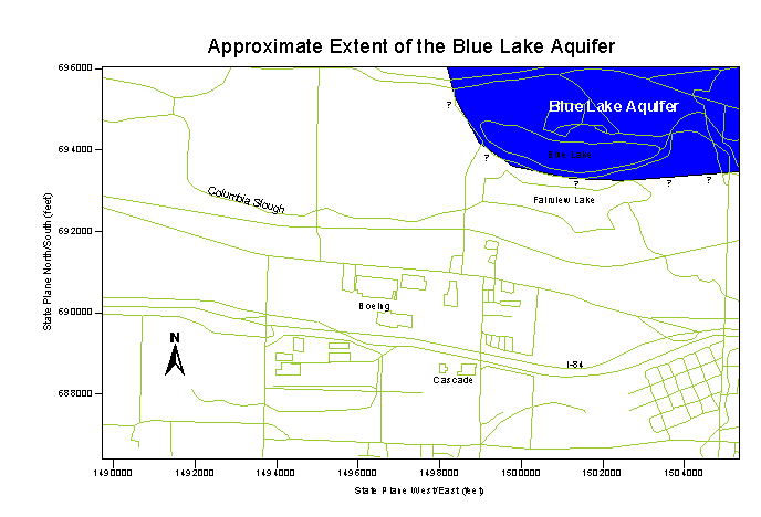
The Interlachen Community and the entire East Multnomah County area sit at the base of the Cascade Mountain Range at the west end of the Columbia Gorge, just south of the Columbia River. The geology is described by a series of flood plain deposits with each unit ranging from 0 to 600 feet thick directly below the area. All of the sediments and sedimentary rocks underlying the Fairview Lake area are fluvial deposits of the Columbia River, deposited on top of the Columbia River Basalt group lava flows over the past 15 million years. Sequencing the layers from top to bottom are the Unconsolidated Sedimentary Aquifer (USA), the Troutdale Gravel Aquifer (TGA), the Confining Unit 1 (CU1), the Troutdale Sandstone Aquifer (TSA), the Confining Unit 2 (CU2), the Sand and Gravel Aquifer (SGA), and the Columbia River Basalts (CRB). Another important unit, which is not part of the top to bottom sequence (it exists laterally to the layered sequence), is the Blue Lake Aquifer (BLA). The order and composition of the sequence is very important in shaping the hydrodynamics of the aquifer system. A brief description of each unit is given below.
Proceeding downward through the sequence of sediment layers, the USA, directly above the TGA, is mainly unsaturated and is mostly a conduit for rainfall infiltration to the lower aquifers. It consists mainly of fine, overbank deposits of sandy silts. The TGA, which is comprised mainly of uncemented gravels, is the first significant aquifer in the sequence and is separated from the TSA by the CU1. The CU1 consists mainly of fine overbank deposits and is considered a leaky aquitard. A leaky aquitard has a much lower ability to transmit water than the layers above and below it, but it is not completely impermeable. The TSA, directly below the CU1, comprises two distinct layers, both of which are fairly permeable. The lower third of the unit is dominantly conglomerate and the upper two-thirds is mainly vitric (glass-like) sandstone. Below the TSA is the CU2 which is very similar in character to the CU1 and results from the same processes (overbank deposits) as the CU1. The SGA is the oldest and deepest aquifer in the sequence and was created from channel deposits from the Columbia River. It consists mainly of sands and gravels with the upper portion tending more towards vitric sandstone. It is highly permeable and is used extensively for water supply purposes. The BLA is not considered part of the sequence since it lies in a lateral path to the layered sediments, cutting through the investigation area almost directly below the Interlachen community (Figure 2). It is considered a young deposit and is the result of cataclysmic floods as the glacial Lake Missoula in Northeast Washington, Northern Idaho, and Western Montana was filled and then quickly and catastrophically drained in response to advancing and retreating ice movements from the last ice age. Because it consists of high-energy flood deposits, the BLA is largely devoid of finer grained materials and thus is the most permeable aquifer in the area. Like the SGA, it is used extensively for water supply purposes.
Characterization of groundwater contamination sites is extremely difficult since the only data available are those from point measurements at the drilling sites of wells and piezometers. Even a site as well studied as the EMC site, which has hundreds of wells in the area, has data that are sparse when compared to the overall extent of the aquifer system. Data are concentrated mainly on the Boeing and Cascade sites, allowing for good geologic representation on those sites. Away from the sites, data become sparser and thus the geologic representation is subject to more interpolation error. The complicated geology below the site adds to the complexity of plume migration.
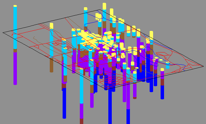
The methodology was to derive the geology directly from well-borehole data by using the data to define contact elevations between each geologic unit (Figure 3). No data from gamma logs were included. Areas with a high density of wells are better characterized than those with a lower density of wells. In addition, the upper layers have more data points since not all wells penetrate all layers in the sequence, thus the upper layers will have a more accurate characterization than the lower layers. The Department of Defense Groundwater Modeling System (GMS) is used to assist in performing the geologic characterization.
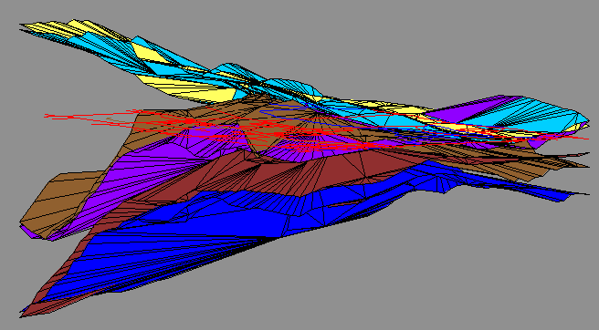
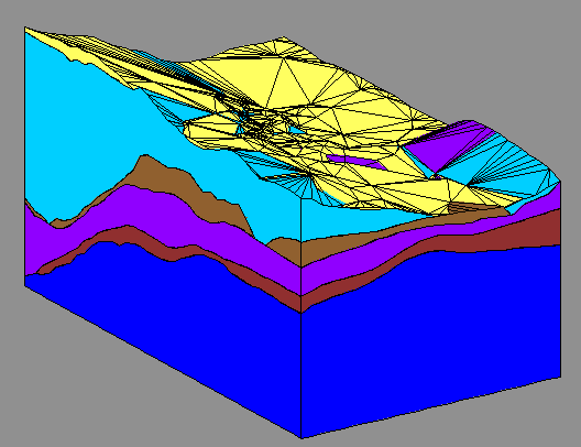
Once the elevations for all the contacts are known, a triangular irregular network (TIN) is created by linearly interpolating between each like contact point from each borehole. Each TIN is a surface representation of the top of each geologic unit (Figure 4). TIN's are created in this manner for each geologic unit in sequence, including a TIN for the ground surface elevations. Since none of the wells used here completely penetrate the SGA, an assumed bottom elevation of -600 ft MSL is used for the bottom boundary of the geologic representation. In order to create cross-sections, three-dimensional representations of each geologic unit are constructed by extruding the space between successive TINS (Figure 5). With the solid representation of each geologic unit, cross-sections can be made to view the geology at any point.
For each borehole used in the characterization, an x and y coordinate (state plane coordinates), a ground elevation, and a depth below the surface for each geologic contact is needed. An MS ACCESS database was created to help with the organization of the vast amounts of data and is coupled with the concentration data as described below. Many data points were inaccurate (i.e., top of the SGA is above the ground level surface) or indefinable (the geology was poorly defined). The latter problem is especially true of wells that were drilled prior to agreed upon definitions of the geology of the basin.
Approximately two-thirds of the borehole data is from Appendix E of EMCON and Landau and Associates (1995) while the rest was pieced together from many different sources. Some errors were found and corrected when they could be verified with other reports or drillers logs. No attempt is made to interpret poorly defined units in the drillers logs. Wells whose geology could not be readily interpreted were excluded from the database. In some cases, geology data are available for certain wells that have no x and y coordinate noted (many drillers logs use a street address for example). For wells such as this, well coordinates are found by placing wells on a map in GMS and noting the x and y coordinate (digitizing). For this reason, and due to the scale of the map used, some wells may be slightly off from their actual coordinates. This was done for about 30 of the 325 wells in the plume area. It is thought that for this visualization project, the relative position of those wells are close enough as to not cause discernable errors in the geologic or plume representations.
The geologic representations agree well with other models and interpretations. The EMC site is very near a geologic 'high', where the layered sequence is arched upward from all directions (Figure 7 through Figure 11). This high area causes a groundwater mound, which retards the plume from migrating in that direction. Consequently, contaminant migration from the Cascade and Boeing sites is mainly north to northeast (Landau and Associates, Prowell Environmental, Pegasus Geoscience, 1998), with some migration approximately eastward around the groundwater mound. Flow direction will vary depending upon the time of the year and the pumping stresses induced in the aquifers.
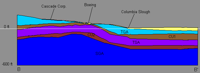
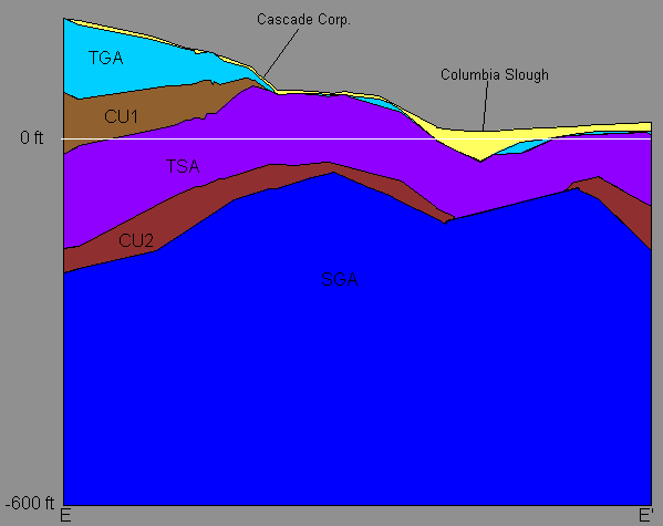
The Cascade site sits on a thin layer of overbank deposits (USA) on top of the TGA at the edge of where the TGA and CU1 terminate (Figure 11). There is concern for contaminate migration from the Cascade site moving northward and 'spilling over' into the lower aquifers at the point where the CU1 is no longer present to protect the TSA. This line, where the TGA is no longer present, is the approximate location of the contaminate collection trench installed to help control this problem. South of the Cascade site, the CU1 is thick enough to effectively isolate the TGA and the TSA from one another. It is where the CU1 and eventually the TGA terminate that causes the numerous springs along the Columbia flood scarp on the north side of I-84.
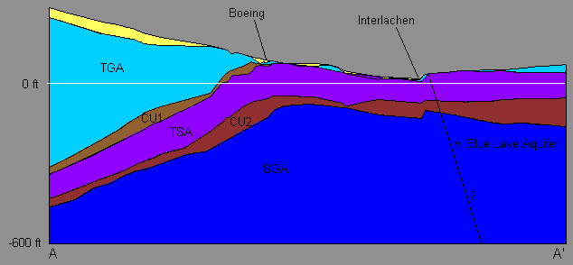
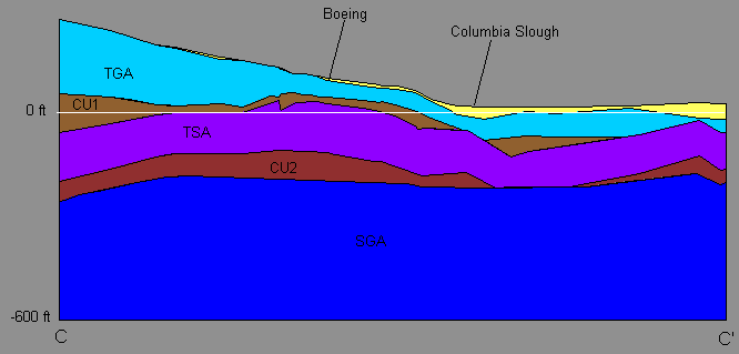
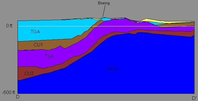
Figure 7 through Figure 11 are cross sections directly through the Boeing site at different angles. The Boeing site sits on a thin layer of the USA, which sits directly on top of the CU1. The CU1 is thin here and does not provide much protection from downward contaminant migration to the TSA. The TSA is known to be contaminated directly below the Boeing site, with TCE concentrations ranging from 0 to about 140 parts per billion (ppb - EMCON and Landau and Associates, RI/FS, 1995). Like the Cascade site, concern for offsite migration via regional flow or pumping induced gradients is high. As contaminant generally moves towards the Columbia River in response to the regional flow from the effects of pumping, contaminated water from the TSA may enter the SGA through a 'hole' in the CU2. Elsewhere, the CU2 is thick enough to protect the SGA from contaminant migration downward from the TSA. It has been shown that in the area of the CU2 hole, the upper SGA is hydraulically connected to the TSA, showing the same magnitude and response to pumping stresses as the TSA (Landau and Associates, Prowell Environmental, Pegasus Geoscience, 1998). Away from the CU2 hole, the SGA acts more independently from the TSA indicating the hydraulic connection is diminished as the CU2 thickens.
Figure 12 through Figure 15 show cross sections locations and animations of stepping through the site one cross section at a time. The animation allows one to see the changing geology as one moves from north to south (Figure 14) and east to west (Figure 15).
Contaminant Plume Visualization
Visualization is different from modeling in that visualization has no ability to factor in the effects of geology on contaminant plume migration. Any attempt to interpolate between data points will not allow for the discontinuities and effects caused by different layering in the geological sequence. Approximately 3000 concentration data points exist over time and space. This report looks only at TCE concentrations since TCE is the only contaminant to be found so far in the SGA (Landau and Associates, Prowell Environmental, Pegasus Geoscience, 1998).
Update reports and databases supplied by DEQ (see references) were used for the contamination data. The maximum concentration from each well sampled from 1996 to the present was used to try and give a better look at the worst case, present scenario of the contaminant plume. Originally, the intent was to visualize a three-dimensional plume, showing both the lateral and vertical extent of the contaminant migration. Since three-dimensional interpolation cannot take into account the effects of the varying geology as mentioned above, it was decided that the contaminant plume would be visualized as a two-dimensional plume in each aquifer.
It was also hoped that the contaminant plume could be shown as it moved over time, however, as sampling frequencies, and the spatial collection of the data changed over time, the coverage area of available data changed also. This produced plumes that were unrealistic, thus using the maximum value for each well from 1996 to the present was the adopted strategy as discussed above.
Ordinary Kriging was used for the two-dimensional interpolation of the plume.
Periodic data reports are issued (usually quarterly) which list the results from the previous periods sampling efforts. Depending upon the source of the report, well names and numbers vary so the consistent matching of data for a single well over time is difficult. To help with this, a unique well number was assigned to each well. Where possible, the PMX number was used. If this was not available, then a number greater than 7000 and less than 8000 was assigned. This set of numbers was used to prevent confusion with existing PMX numbers or numbering from the USGS system. The concentration data is kept in a separate database from the geology data, which was also assigned the same unique well numbers. This allowed flexibility in the query and use of the data.
Because of the large number of data points (>3000), not each data point can be explicitly plotted. Instead, simplifying assumptions needed to be made to reduce the number of data points used in the visualization. To construct the two-dimensional plume for each aquifer (see results section), the maximum concentration 'hit' in each well was used from the period of January 1, 1996 to May 31, 1998. Also, to prevent interpolation from 'rounding' the plume south of the Cascade site, interpolation boundaries were set to truncate the plume along an east/west line just south of the Cascade site. For the time series plots, the average concentration in each well is used for each year plotted.
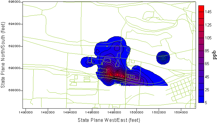
Figure 16 and Figure 17 show the contaminant plume in the TSA and the SGA respectively. Not surprisingly, the extent of the contamination in the TSA is much greater than in the SGA due to the fact that the TSA is a shallower aquifer and the CU2 provides a protective layer to help prevent contaminant migration from the TSA to the SGA. The sources of contamination into the SGA are most likely: 1) downward vertical migration from the TSA through the hole in the CU2, and 2) leakage down existing boreholes and well casings from contaminated units above (Landau and Associates, Prowell Environmental, Pegasus Geoscience, 1998).
The contamination data exist as a three dimensional scatter point system meaning each data point has an x, y, z, and concentration attribute associated with it. Projections of the scatter data onto selected cross sections are shown in Figure 18 and Figure 19. From these plots, the extent and magnitude of the concentration plume can be easily seen.
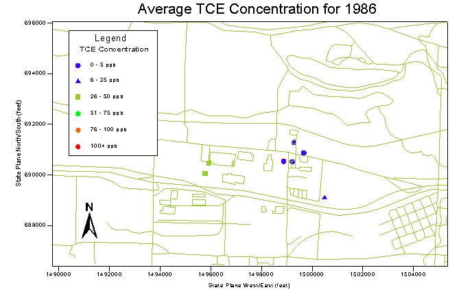
Figure 20 shows an animation of the time averaged concentration in each well sampled for each year from 1986 to 1997. From these plots, the spatial change in sampling can be seen as well as growth in the number of sampling points. In most cases, each point is sampled many times over the course of a year.
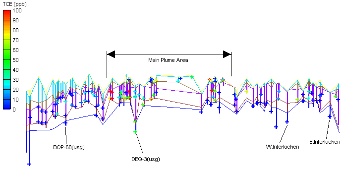
It is not possible to accurately represent a three dimensional plume on a two-dimensional surface. Different projections can give different views, none of which are entirely accurate. To help overcome this, the three-dimensional data was converted to a two-dimensional image. This was done by ordering the data first on its X coordinate and then on its Y coordinate. The distance between each data point was calculated and then used as the X coordinate in the two dimensional representation. This is shown in Figure 21 and Figure 22. Figure 21 shows the order and the line of data used and Figure 22 shows each data point, the boreholes, and the stratigraphy. Figure 23 and Figure 24 show close ups of the left-hand side and the right-hand side respectively, of Figure 22. It can be seen that the majority of the sampling points are in the TSA, with only a small percentage in the SGA. Also note that the lower SGA is shown to be below detection limits for TCE.
The intent of this visualization project is to provide a graphical and visual tool for the education and interpretation of the conditions at the EMC site and the surrounding vicinity. Any conclusions or interpretations are stated to help in the overall understanding of the dynamics at the site and may change as future data and work become available. The complicated geology makes direct interpolation of the data impossible since direct interpolation will not allow for the effects of geology on the plume shape. Reconstructing the history and modeling the plume migration given the known geology would reproduce the actual three-dimensional shape of the plume better than direct visualization of the data.
Direct visualization of the data is useful however, in the education and understanding of the site. From this visualization we can see:
Figure 1 - Map of East Multnomah County contamination site showing the location of the potential responsible parties (Boeing and Cascade Corp.), and the Interlachen community.
Figure 2 - Plan view of East Multnomah County Site showing the approximate extent of the Blue Lake Aquifer (BLA). The BLA is a comparatively young deposit being the result of scouring and deposition during the high-energy Missoula floods. The actual contact point between the BLA and the rest of the aquifer/aquitard system is not exactly known.
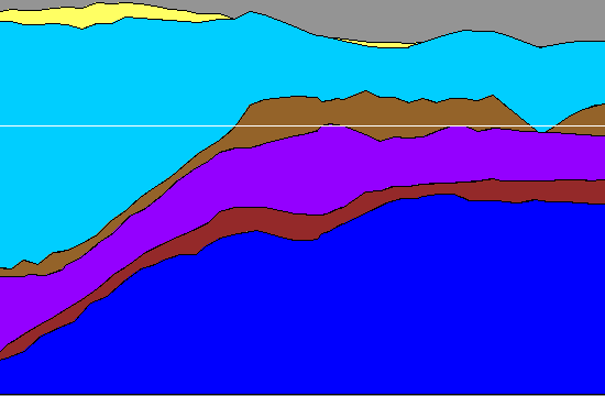
Figure 3 - Oblique view of borehole data used to delineate the EMC stratigraphy. Each contact elevation between successive geologic layers is used to create a surface representation of each geologic unit. Fairview and Blue Lakes are in the right hand corner of the tilted map. Yellow - USA, Light Blue - TGA, Light Brown - CU1, Purple - TSA, Dark Brown - CU2, Bright Blue - SGA.
Figure 4 - The Triangular Irregular Network (TIN) for each geologic unit as constructed from the borehole data (see Figure 3). Each TIN represents the surface elevation of each geologic unit. Yellow - USA, Light Blue - TGA, Light Brown - CU1, Purple - TSA, Dark Brown - CU2, Bright Blue - SGA.
Figure 5 - Solids view of the EMC site. Each TIN (Figure 4) is extruded downward to the next TIN to create a solid representation of the geology of the area. Fairview and Blue Lakes are lie in the right hand corner of the solid. Yellow - USA, Light Blue - TGA, Light Brown - CU1, Purple - TSA, Dark Brown - CU2, Bright Blue - SGA.
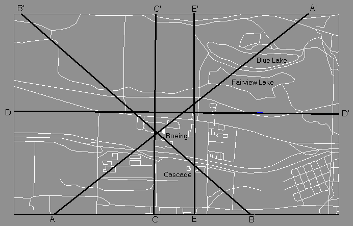
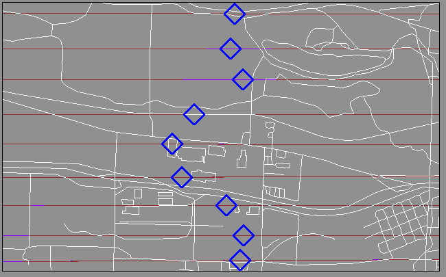
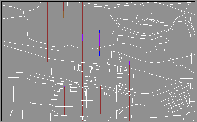
Figure 6 - Plan view of EMC site showing cross section locations for Figure 7 through Figure 11. See Figure 2 for scale.
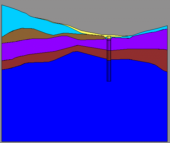
Figure 7 - Cross section along A-A' (see Figure 6). Representation of geology to the right of the Blue Lake Aquifer interface does not reflect reality since this area has been scoured away and filled with high-energy flood deposits. Note the upward sloping geology in all directions below the Boeing site. The CU2 shows thinning between the Boeing site and the Interlachen community which may create a pathway for contamination to move between the TSA and the SGA.
Figure 8 - Cross section along B-B' (see Figure 6) through the Cascade and Boeing sites. Note that the USA (yellow), TGA, and CU1 are thinning between the Cascade site and the Boeing site. This may create pathway for contaminants from the TGA to enter the TSA. The geologic 'high' can be seen by the general upward sloping strata from all directions underneath the Boeing site.
Figure 9 - Cross section along C-C' (see Figure 6) on a North/South line through the Boeing site. Note where the CU2 thins and becomes non-existent, creating an area of communication between the TSA and the SGA. This may have large implications on long term plume migration.
Figure 10 - Cross section along D-D' (see Figure 6) along an west/east line through the plume area. The 'pinching' out of the TGA and the TSA is evident here. This may allow for a more direct pathway for contamination to enter the lower aquifers.
Figure 11 - Cross section along E-E' (see Figure 6) on a north/south (E'/E) line directly through the Cascade Corp. site. The site sits on the edge where the TGA and the CU1 pinch out, which creates a direct pathway for contamination to enter the TSA and the lower aquifer system.
Figure 12 - Plan view of EMC site showing cross section locations for animation in Figure 14.
Figure 13 - Plan view of EMC site showing cross section locations for animation in Figure 15.
Figure 14 - Successive cross sections as defined in Figure 12 along an east/west line. Start of sequence is when the ground surface is the highest.
Figure 15 - Successive cross sections as defined in Figure 13 along a south/north line. Start of sequence is when the ground surface is the highest.
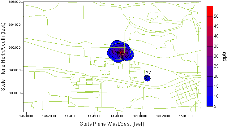
Figure 16 - Two-dimensional plume in the TSA. Multiple completion wells use the maximum concentration for all data points. The isolated plume to the right of the main plume is from a 5/7/98 sampling of PMX-189 (Fairview RV Park - 57 ppb) and appears to be discontinuous from the main plume at this point. The extent of the plume around PMX-189 is strictly from interpolation and should not be construed as reality.
Figure 17 - Two-dimensional plume in the SGA. Multiple completion wells use the maximum concentration for all data points. The isolated small plume to the lower right is from a single hit in MW-37(usg) on 12/3/96 of 23 ppb. This has not been detected before or since. With the exception of DEQ-3(usg) in the hot spot of the main plume (59 ppb), all other hits are below 16 ppb, with most being below 7 ppb.
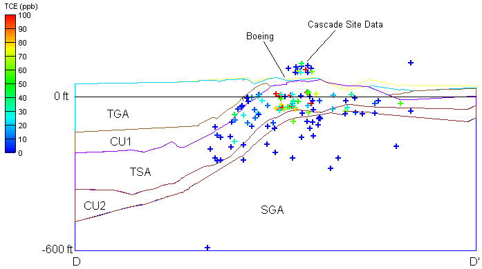
Figure 18 - Cross section along D-D' (see Figure 6) showing three-dimensional scatter data superimposed. The scatter data, which exist in three dimensions, are projected horizontally onto the D-D' cross-section. Since the stratigraphy is sloping downward into the page (towards the north), some data points will not be projected onto the aquifer in which they exist. This is why the Cascade Corp. data appear to the floating. Note the plume area in the TSA underneath the Boeing site.
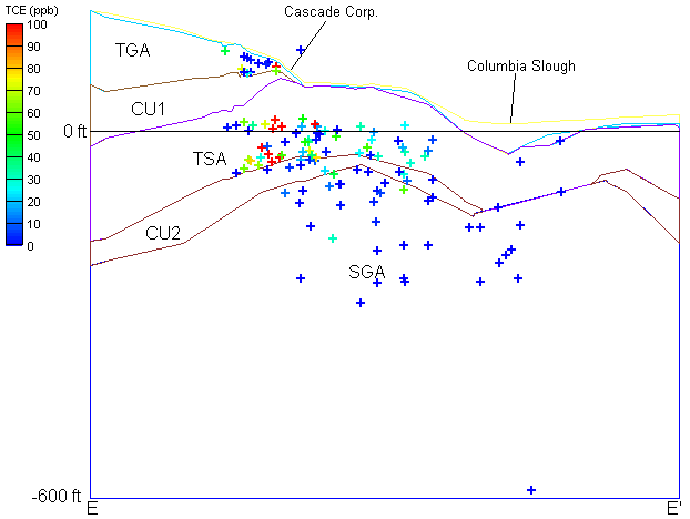
Figure 19 - Cross section along E-E' (see Figure 6) showing three-dimensional scatter data superimposed. The scatter data, which exist in three dimensions, are projected horizontally onto the E-E' cross-section. Since the stratigraphy is sloping downward into the page (towards the west), some data points will not be projected onto the aquifer in which they exist. Note the large concentration of data in the TSA as well as the extent of the positive TCE concentrations.
Figure 20 - Time averaged concentration in each well sampled from 1986 to 1997. Some points show data from multiple completion wells thus a low and high concentration may show at a single point.
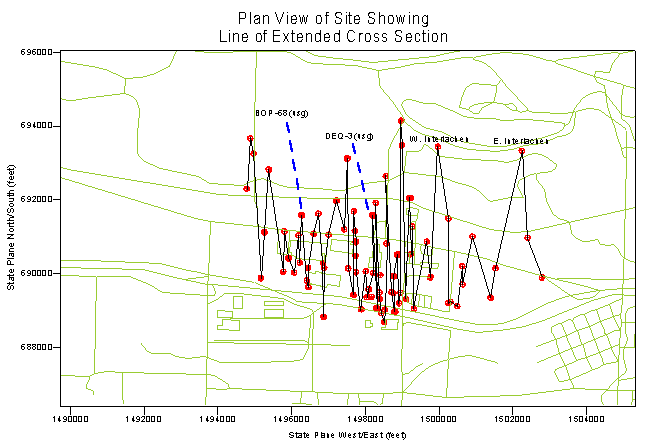
Figure 21 - Line of extended cross section for Figure 22 through Figure 24.
Figure 22 - 'Extended' cross-section showing data points, borehole data, and connected stratigraphy. Data point color varies according to TCE concentration. Note how most of the collected data is in the TSA, with most of the higher hits in the upper TSA. Due to the zig-zag nature of the cross section (see Figure 28) geologic interpretation is not valid here. The plot represents the straightening of the zig-zag line shown in Figure 28, from left to right. Some wells in this view are masked by wells that are immediately adjacent to each other.
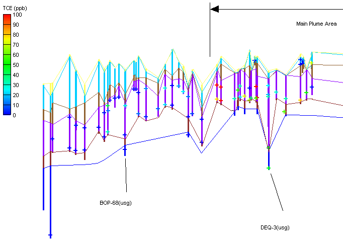
Figure 23 - Close up view of the left-hand side of Figure 22. Data points from multiple completion wells can be seen.
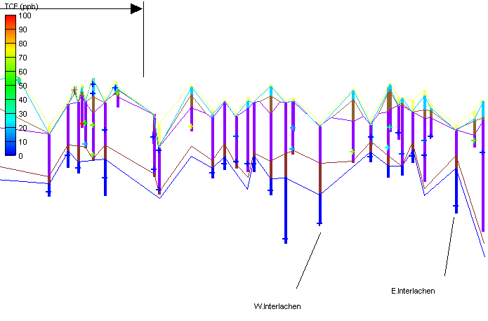
Figure 24 - Close up view of the right-hand side of Figure 22. Data points from multiple completion wells can be seen.
TSA Action Plan Troutdale Sandstone Aquifer East Multnomah County, Oregon; Landau Associates, Inc., Prowell Environemental, Inc., Pegasus Geoscience, Prepared for The Boeing Company and Cascade Corporation, May 29, 1998
March 1998 Progress Report – TSA Remedy Implementation, East Multnomah County; Letter to Bruce Gilles, Oregon Department of Environmental Quality from Prowell Environmental, April 15, 1998
Pilot Well PMX-140 Troutdale Sandstone Aquifer East Multnomah County, Oregon; Landau Associates, Inc., Prepared for The Boeing Company and Cascade Corp., April 14, 1998
Troutdale Sandstone Aquifer Remedy – Phase 2B Technical Memorandum East Multnomah County Portland, Oregon; EMCON, Prepared for Cascade Corporation, April 3, 1998
Preliminary PMX-189 Remedy Recommendations Troutdale Sandstone Aquifer Remedy East Multnomah County; Pegasus Geoscience and Prowell Environmental, Prepared for Cascade Corp. and The Boeing Company, March 31, 1998
Revised System Optimization and Performance Evaluation Plan Troutdale Sandstone Aquifer East Multnomah County, Oregon; Landau Associates, Inc., Prowell Environemental, Inc., Pegasus Geoscience, Prepared for The Boeing Company and Cascade Corporation, March 31, 1998
Supply Well Assessment – Troutdale Sandstone Aquifer Remedy; Letter to Bruce Gilles Oregon Department of Environmental Quality from EMCON, March 3, 1998
4th Quarter 1997 Troutdale Sandstone Aquifer Quarterly Data Report The Boeing Company; Landau and Associates, Inc., February 27, 1998
October, November, and December 1997 Troutdale Sandstone Aquifer (TSA) Field Sampling Data and Laboratory Reports, Cascade Corporation, TSA Remedy Implementation Work; Letter to Bruce Gilles Oregon Department of Environmental Quality from EMCON, February 26, 1998
October, November, and December 1997 Troutdale Gravel Aquifer (TGA) Field Sampling Data and Laboratory Reports, Cascade Corporation; Letter to Bruce Gilles Oregon Department of Environmental Quality from EMCON, February 26, 1998
SGA Action Plan, Troutdale Sandstone Aquifer, East Multnomah County Oregon; Landau Associates, Inc., Prowell Environemental, Inc., Pegasus Geoscience, Prepared for The Boeing Company and Cascade Corporation, February 2, 1998
Report on Construction and Testing of Groudnwater Extraction Wells EW-6, EW-7, and EW-9 and Construction and Sampling of Monitoring Wells BOP-44(usg) and BOP-69(usg), Troutdale Sandstone Aquifer (TSA) Action Phase 2A Boeing Portland; AGI Technologies Water Resources Group, Prepared for The Boeing Company, August 22, 1997
Remedial Design and Remedial Action Work Plan Troutdale Sandstone Aquifer East Multnomah County, Oregon; EMCON and Landau and Associates, Inc., Prepared for Cascade Corp. and The Boeing Company, June 19, 1997
Technical Report EWR-5-97; Portland State University, Department of Civil Engineering, Prepared for the Friends of Blue and Fairview Lake, June 11, 1997
1996 Annual Performance Report Troutdale Gravel Aquifer Cascade Corporation; EMCON, Prepared for Cascade Corporation, March 14, 1997
Final Report Remedial Investigation and Feasibility Study Troutdale Sandstone Aquifer, Part 1 Remedial Investigation and Part 3 Feasibility Study; EMCON and Landau Associates, Inc., Prepared for Cascade Corporation and The Boeing Company, October 6, 1995