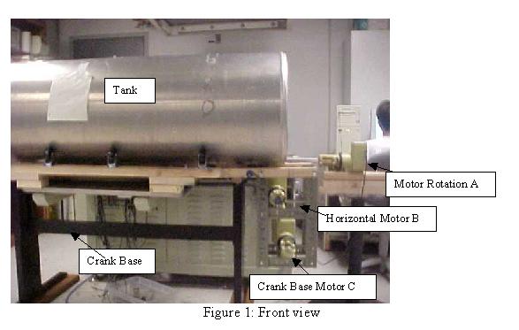
The robot includes three main parts: a rotation frame, crank base, and control box.
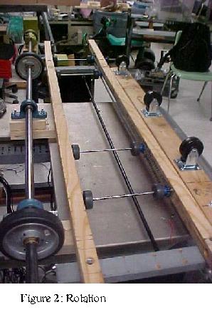
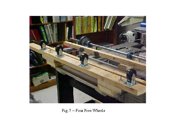
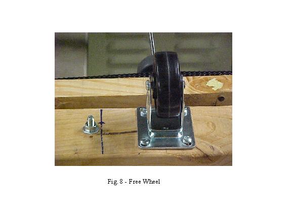
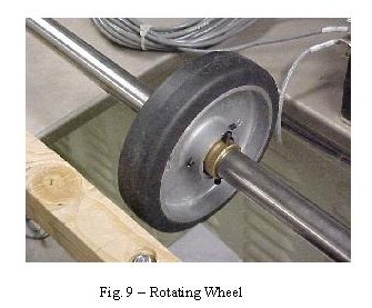
1. Rotation Frame: including four free wheels, two rotating wheels connected to the motor A by a stainless steel shaft. Its function is to rotate.
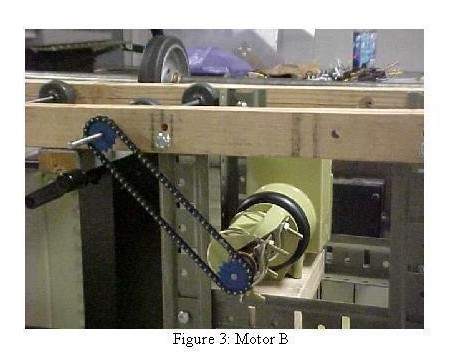
2. Crank Base: including conveying wheels connected by a chain and sprockets that is connected to the motor B to move the tank horizontally and the motor C moves the crank base up and down.

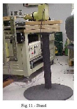
And the motor A is placed on the black stand. Look at it on the figure 11.
II. Crank Base:
How to assemble the crank base: see the manual
on figures 12-1, 12-2, 12-3, & 12-4

Figure 12-1

Figure 12-2

Figure 12-3

Figure 12-4
The following picture will show you how to place the conveying frame on the crank base.
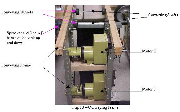
The conveying frame is placed on the top the crank base as shown on the figure above. The conveying wheels and sprockets are connected to the shafts by 2 screw sets and super blue (look at the figure 14).

The chain A connects and rotates all sprockets to move the tank to the left and right.
Each conveying shaft is places on 2 ball bearings at the ends that are placed inside the two pieces of wood. Look at it on the figure 15.

The motor B rotates to move the tank to left and
right.
The motor C rotates to move the tank up and down.
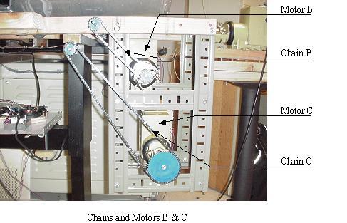
Each motor has three wires 1, 2, & 3 that are connected to the three outputs of the motor controller, respectively.
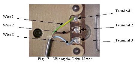
- Snap open the drives cover using a coin or
screwdriver
- Separate the cables three wires about 1½
inches down the cable and strip off about ½ inch of insulation from
each wire.
- Connect the wires to the terminals. CAUTION:
be sure there ara no loose strands of wire that can short between terminals.
- Close the cover securely.
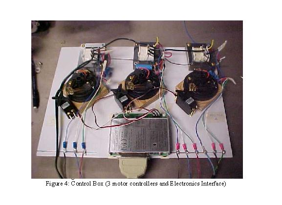
III. Control Box:
There are a Robix RCS-6 electronics interface
and three motor controllers A, B, & C, power supplies for controllers
and interface, a printer cable connecting from PC to the electronics interface.
Each motor controller has a switch, a servomotor, and a voltage transformer.
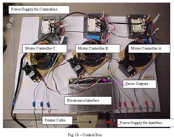
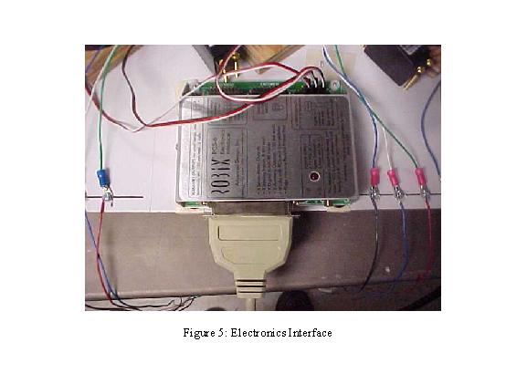
1. Electronics Interface:
Communicating between the PC and the motor controllers.
It is connected to the PC by a printer cable and supplied by a power of
12 VDC, 1A. The servo outputs 1, 3, and 5 are used to connect
to three servos as shown above.
How to connect and set up the interface:
Connects to IBM PC's and compatibles through printer port using your existing printer able. No need to open your computer. Works with laptops, too.
Two on-off outputs for device control. Use these outputs to provide up to about 150 ma of drive current for LED's, postage stamp motors, etc.
Sensor inputs for advanced users. Most useful when you are controlling your robot from C or QB4.5, where your programs can make decisions based on sensor readings. See the Sensors section for information on making or buying sensors.
- 8 channel 8 bit analog-to-digital converter
(ADC) lets you add sensors such as photodetectors, thermistors, potentiometers.
See the chapter on "Sensors".
- 7 switch-closure inputs can be used for simple
sensors with user-supplied switches.
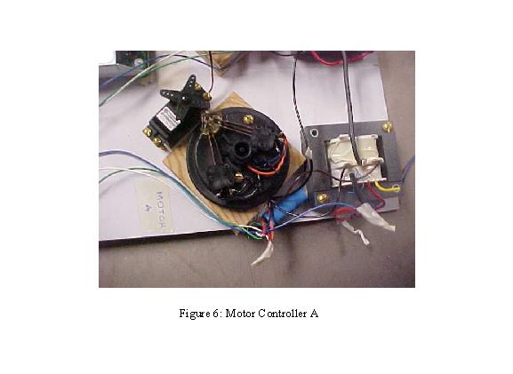
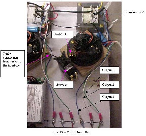
2. Motor Controller:
+ Switch: changing the rotation of the motor (clockwise and counter-clockwise).
+ Servomotor: it is a motor that rotates half circle for maximum.
It is used to turn on/off the switch.
+ Voltage transformer: it is used to change the current and voltage from
the power supplied to output an AC with 120 volts and 60hz to supply to
the motor.
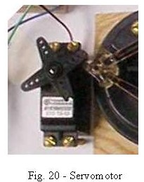
a. Servomotor:
The Hitec STD TS-53 servo has three leads colored
white, red, and black and terminated in a thin .1" center female header
connector. (Other servos may have different colors and connectors but the
overall scheme is the same.) The red lead connects to positive voltage
(servos are rated for 5-6 volts) on the RCS-6 Adapter, the black lead is
common, and the white (or yellow) lead carries control pulses from the
controller to the servo.
There is no feedback from the servo back to the
controller. There is a feedback system, using a potentiometer as the encoder
within the servo itself that allows it to maintain the position that the
controller dictates.
<- shorter longer -> (Hitec and others)
o o
o o
o
o
o o
o
o
o
o o
o o
Within the servo as each pulse is received its width is "measured" and "compared" to the servo's position. If the servo's position does not match the position implied by the pulse width, the servomotor is turned on for a few milliseconds (pulsed) to bring the servo closer to the proper position. Since the command pulses are coming in a continuous stream, at approximately 80 pulses per second, the servomotor is continually pulsed closer to the desired position until it is reached.
To move the servo smoothly from point to point the RCS-6 Adapter sends a continuous stream of control pulses whose widths will be increasing over time for counter-clockwise motion or decreasing for clockwise motion.
How to connect servomotor to the electronics interface:
Plug your robots servos into the interface on the header pins marked Servos. If you dont have a robot assembled yet, but have some servos, just plug the servos in.
The servos plugs mate to the sets of three pins at the connector marked servos on the interface. Dont plug them into the sets of two pins on the ends of the servos pin group, they dont work. NOTE that the white servo wires go on the inside edge of the interface, while the black wires go on the outside.
Reference:
If you damage, wear out, or lose a servo, or
just want spares, here's how to get the best prices on replacements.
Go to the Robotics Lab, room 70, in FAB or call Dr. Perkowski at (505)
725-5411.
b. Switch:
The servomotors blade rotates 30 degree, clockwise,
to push the switch button, then the bars contact together and turn on the
motor to rotate clockwise. When the servomotors blade gets to back
the original and turn off the motor. Reversibly, the servomotors
blade rotates 30 degree, counter clockwise, to turn on/off the motor to
rotate counter clockwise.
