About Electricity
and
Power
Harry H. Porter III, Ph.D.
January 16, 2008
This document is on the
web at
www.cs.pdx.edu/~harry/musings/AboutElectricity.pdf
and
www.cs.pdx.edu/~harry/musings/AboutElectricity.htm
Table of Contents
What is “VOLTAGE”?.......................................................................................... 4
What is “GROUND”?............................................................................................ 4
How can you measure voltage?............................................................................... 4
What is a MULTIMETER?.................................................................................... 5
What is ELECTRICITY?....................................................................................... 5
Can you see electricity?.......................................................................................... 5
What is a BATTERY?........................................................................................... 6
What is a CIRCUIT?.............................................................................................. 6
What is CHARGE?................................................................................................ 7
What about POSITIVE charges?............................................................................. 8
How strong is the force of electric charge?............................................................... 8
Do we ever feel the electric charge?......................................................................... 8
What does CHARGE have to do with ELECTRICITY?............................................. 9
Which way does electricity flow?............................................................................ 9
What is CURRENT?............................................................................................ 10
What is ELECTRIC CURRENT?.......................................................................... 11
Which way does current flow?.............................................................................. 11
Is POWER the same as ENERGY?........................................................................ 12
What is POWER?................................................................................................ 12
How do you compute power?................................................................................ 14
What is ENERGY?.............................................................................................. 15
What about ENERGY-EFFICIENT appliances?...................................................... 16
Can electric space heaters be energy-efficient?........................................................ 16
What is an electric space heater?............................................................................ 17
What does ENERGY-EFFICIENT mean?.............................................................. 17
Would POWER-EFFICIENT be a better term than ENERGY-EFFICIENT?............. 17
Can you use waste heat as a measure of energy-efficiency?....................................... 18
How can you measure the power consumed by a light bulb?..................................... 18
How do you measure current through a device?....................................................... 18
What is RESISTANCE?....................................................................................... 19
What is the water analogy for voltage?................................................................... 19
What is the water analogy for resistance?................................................................ 20
What is a RESISTOR?......................................................................................... 21
How are resistors rated?........................................................................................ 21
How are VOLTS, AMPS, and OHMS related?........................................................ 22
What happens if you connect two resistors in series?................................................ 24
What is the resistance of two resistors connected in series?....................................... 24
Why are some batteries large and some batteries small?............................................ 25
Why are several batteries used together?................................................................. 25
What happens when you connect batteries in series?................................................. 25
What if you connect the two ends of a battery together?........................................... 26
Why should a battery not be allowed to get hot?...................................................... 27
What is a DIODE?............................................................................................... 27
What is the water analogy for the diode?................................................................ 28
What is the circuit diagram for a diode?................................................................. 28
What do diodes look like and how can you tell which end is which?.......................... 28
How can I remember which way diodes conduct?.................................................... 29
What is an LED?................................................................................................. 29
What is DIRECT CURRENT (DC)?...................................................................... 30
What is ALTERNATING CURRENT (AC)?.......................................................... 30
What is a RECTIFIER?........................................................................................ 31
How does a rectifier work?................................................................................... 32
How can you measure the power output of a generator?........................................... 34
What are OPEN VOLTS?..................................................................................... 35
What is a LOAD?................................................................................................ 35
Why measure open voltage?.................................................................................. 35
What is the procedure for measuring voltage?......................................................... 36
How do you measure DC voltage?......................................................................... 36
How do you measure AC voltage?......................................................................... 37
How can you measure resistance?.......................................................................... 37
How do you measure the resistance of a coil?.......................................................... 38
How can you get more power from a generator?..................................................... 38
How efficient is a generator?................................................................................. 39
How do you calculate the power output of a generator?............................................ 39
If you want a given amount of power, how fast do you have to turn the
generator?..... 42
What is “VOLTAGE”?
Voltage is always measured as
a difference between two points in a circuit. It is a relative number. For example, point A in the circuit might be 5 volts greater
than point B.
To measure voltage, place the
two probes of your multimeter on points A and B. This measures the difference in voltage between point A and
B.
The voltage all along a
single wire will be the same. In
other words, if you try to measure the voltage between two points that are
connected with a wire, the relative voltage difference will be zero. [Exception: extremely high currents are
causing the wire to get warm. Then
the wire is starting to fail. It
is no longer a perfect conductor.]
What is “GROUND”?
To make voltage measuring
easier, some point in a circuit is usually labeled “ground”. The voltage level of ground is always
assigned a value 0.0V and all other voltage measurements are relative to this reference point.
All points of the circuit
that are directly connected by wire to ground are also called ground. Therefore, ground is really a
collection of wires in the circuit that are all connected. All points along ground will have the
same voltage (because they are connected by wire).
By definition, all ground
points have zero voltage.
How can you measure voltage?
Voltage is usually measured
relative to “ground”; that is, voltage is measured relative zero. The voltage of some point X might be a
positive number or might be a negative number. In many circuits, the voltage at point X will change over
time.
To measure the voltage of
some point X in a circuit, connect the black probe from your multimeter to
ground. Then connect the red probe
to X (the point you are interested in) and read the voltage level from the
meter. Since ground is always at
zero volts, the red probe will measure the voltage at point X. Technically, this voltage is relative
to the ground, but usually the voltage at point X is usually just expressed as
a number. For example, if X is
12.0 volts greater than the voltage at the place called “ground”, then we say
that the voltage at X is +12.0V.
What is a MULTIMETER?
A multimeter is the most
basic tool in all electrical and electronic tinkering. Get one.
A multimeter can measure
these things:
voltage
(in Volts)
current
(in Amps)
resistance
(in Ohms)
A multimeter can test things
like batteries, light bulbs, and household outlets. It can also be used to evaluate electrical circuits.
What is ELECTRICITY?
Tiny particles called
ELECTRONS move through wires, just like molecules of water move through a
pipe. A WIRE is like a PIPE. An ELECTRON is like a MOLECULE of water.
Can you see electricity?
No. The electrons are way too small!
Electrons are even smaller
than the particles of light.
(Particles of light are called PHOTONS.) Trying to see electrons with light would be like trying to
find a marble by throwing pillows at the marble and watching how they bounce
off the marble; the pillows
(photons) are way too big and fluffy compared to the marble (electron).
Even with better microscopes
and more powerful lenses, it will always be impossible to directly see an
electron.
What is a BATTERY?
A battery is just like a pump
that is turned on. A pump pushes
water through a pipe.
The pump sucks water into its
INPUT side and pushes water out its OUTPUT side.
A battery pushes electrons
out one end and sucks electrons back into the other end.
What is a CIRCUIT?
Imagine a bunch of water
pipes connected in some complex way to a pump. The pump pushes water through the pipes. But the water has to get back to the
pump. For every liter of water the
pump pushes out, a liter of water must flow into the input of the pump. And for every liter that flows into the
pump, a liter must flow out of the pump.
The pipes start from the
pump’s output and go all around and then finally, they join together and lead
back to the pump’s input. In the
simplest case, a single pipe runs from the pump’s output right back to the
pump’s input. In more complex
cases, there can be a lot of pipes and maybe some other things between the
pump’s output and the pump’s input.
In the complex case, there may be many ways for the water to flow back
to the pump. But it will always be
true that each liter of water pushed out by the pump must find its way back to
the pump’s input.
The pump and all the pipes
constitute a “circuit”. In the
case of electricity, the battery, the wires and the other stuff (like lights,
switches, resistors, etc.) all constitute a circuit. Look at the wires and try to imagine little pipes carrying
electrons. Every electron that
leaves the battery’s output must find a way to get back to the battery’s input.
What is CHARGE?
Each electron carries a
charge, but what exactly is an electron like? First, an electron is very, VERY, VERY small, so it is hard
to imagine. But let’s imagine enlarging
a couple of electrons and imagine what their charge would feel like.
First, remember how magnets
feel. Each magnet has a NORTH end
and a SOUTH end. I’m sure you
remember that a NORTH POLE will be ATTRACTED to a SOUTH POLE. And you remember that two NORTH POLES
will REPEL each other. Also, two
SOUTH POLES will REPEL. With
magnets, we say: “Opposites attract and likes repel.” Also,
remember how the STRENGTH of the magnetic effect is stronger when the two
magnets are close together. As you
move the magnets away from each other, the effect becomes weaker and weaker.
Now imagine enlarging
electrons until they are as large as baseballs. Imagine that you are holding two electrons, one in each
hand, like two baseballs. First,
notice that they are round:
electrons are perfectly spherical.
This is very different from a magnet. Even if you have a magnet that is spherical in shape, it
will still have a north end and a south end. But electrons are really spherical.
Each electron carries a
NEGATIVE charge. With magnets, we
use the terms NORTH and SOUTH; with electrons and charge, we use POSITIVE and
NEGATIVE. The rule for CHARGE is
the same as for the magnetic force:
“Opposites attract and likes repel.” Imagine that you are holding one electron in each hand. Now, slowly bring them close
together. They REPEL each
other. The electrons feel pretty
much like magnets. The closer they
get to each other, the harder they push away from each other. The repellent force between charges is
very similar to the force between magnets, but it is an entirely different
force. The electric force is not
the magnetic force.
There is another difference
between electrons and magnets.
With magnets, you can change the force by turning or twisting the
magnet. If two magnets are
repelling each other, you can turn one of them around and then they will suddenly
be drawn toward each other. As you
know, one magnet can even cause another magnet to twist or turn or flip
over. With electrons, there is no
such effect. You can rotate the
electron in your right hand, but it will still repel the electron in your other
hand exactly the same amount. All
that matters is how far apart they are.
What about POSITIVE charges?
Each electron has a NEGATIVE
charge. There is a particle called
a PROTON which has a positive charge.
Imagine that you have two protons, one in each hand, and they have been
enlarged to be the size of baseballs.
The two protons will repel each other, just like the two electrons
repelled each other.
Now imagine that you have an
electron in one hand and a proton in the other. Since they have opposite charges, they will be attracted to
each other. They closer you get
them, the stronger they will pull toward each other.
There are other particles
that have electric charges, and there is a lot more to charge than I’ve
discussed here. One reasonable
question is “How is the force of charge transmitted between the electrons and
protons?” Perhaps you’ve also
wondered “How is the magnetic force transmitted between two magnets?” Sure, two magnets feel a force (either
attractive or repulsive), but how does one magnet even “know” there is another
magnet nearby.
These are deep and subtle
questions, with mysterious and profound answers.
How strong is the force of electric charge?
The electric force has about
the same strength as the magnetic force. The magnets you hold are large, but if you imagine shrinking
them to the size of electrons their force would also be shrunk and would become
very tiny. Electrons are very
small, so they naturally have very small forces.
If you removed all the
electrons from, say, an apple and put them together to make a giant electron,
you’d be able to feel the electric charge very easily.
Do we ever feel the electric charge?
Occasionally you might feel
the electric charge. We call it
“static electricity”. One simple
trick to demonstrate the force of the electric charge is to rub a balloon on
your hair, and then stick the balloon to the wall. The force that holds the balloon to the wall is similar to
the magnetic force, but it is really the force of electric charge.
What does CHARGE have to do with ELECTRICITY?
Not a whole lot. But it is
important to know that electricity is nothing more than flowing electrons.
When you push electrons in
one end of a wire (i.e., a pipe), then the repulsive force between negatively
charged particles causes this electron to push on the next electron. That electron will then push on the
next electron and so on, all the way down the wire, until an electron is pushed
out the other end. This is
electricity.
Which way does electricity flow?
Electrons flow FROM the
NEGATIVE end of a battery through the circuit and reenter the battery on the
PLUS end.
Early scientists had
difficulty detecting electrons.
They GUESSED that electricity was the flow of POSITIVE charges from the
positive side of a battery toward the negative side, but these early scientists
were WRONG. Being pretty upbeat
people, they named the side where they thought the positive particles were
coming from “POSITIVE.” We still
call that side of the battery POSITIVE, but we now know that the flow of
electrons is really the reverse.
Imagine that you have a pipe
(such as a straw) filled with water.
Now imagine that you push water into one end, which we’ll call the
negative end. What happens? Well, water will come out the other
end. Water is pushed into the
NEGATIVE end and water comes out the POSITIVE end. Now imagine that instead of pushing water into the negative
end, you suck water out of the positive end. What happens?
The same thing! Water goes
into the negative end and comes out the positive end. In terms of getting water to move through the pipe, it
doesn’t matter whether you push it into the negative end or whether you pull it
out the positive end.
The exact same is true of
electricity! The electrons can be
pushed from the negative side of the battery or they can be sucked from the
positive end. Either way, the
electrons flow in the same direction.
In fact, it really takes both the pushing and pulling in order for
electricity to flow. Electrons are
pushed out the negative side of the battery and, at the same time, they are
sucked back into the positive side of the battery.
With water, if you have one
end of a pipe connected to a pump, pushing water into the pipe, and the other
end of the pipe is disconnected, then water will flow. Water will flow into the front of the
pipe and then will flow out the other end, all over the floor.
With electricity, it is
different. The electrons will not
simply come out the end of the wire and fall on the floor! The electrons have to stay in the
metal; they can’t leave the metal.
So when you disconnect a wire, it is more like disconnecting a pipe AND
PLUGGING the pipe up, so that water cannot leak out.
No matter how hard the pump
pushes water into one end of a pipe, the water will not flow if the other end
is plugged. The same is true with
electricity. If the circuit is
broken, then the electrons cannot flow, not matter how hard the battery
pushes. This explains why it
doesn’t matter whether you disconnect the battery’s positive connection or its
negative connection. A break
anywhere in the circuit will stop flow everywhere!
What is CURRENT?
Imagine a pipe and imagine
that water is flowing through that pipe.
How much is flowing?
Perhaps it is 1 liter per minute.
If you suddenly cut the pipe and held it over a bucket, you could
measure how much water flowed out.
If a liter-sized bucket is filled in one minute, then we know the rate
of flow. Even if we don’t cut the
pipe, we can still measure the flow through the pipe. For example, we can make a pencil mark on the pipe and talk
about how much water flows past that point each minute.
Now imagine that we double
the flow to 2 liters per minute.
Now the pipe is carrying twice as much water past our pencil mark every
minute.
How can we increase the flow
through the pipe? Two ways! First, the water could travel
faster. In the water speeds up and
is now moving at double the speed as before, then twice as much water will flow
past our pencil mark.
What is the second way to
double the flow? Simple! Let’s keep the speed of the water the
same as before, but increase the size of the pipe instead! So if the speed of the water is the
same, but the size of the pipe is doubled, then the flow will be doubled. (Technically, we need to double the
cross-sectional area of the pipe, not simply double the pipe’s diameter.)
Notice that it takes two
things for current: water speed and pipe size. Increasing either will increase the current flow. Likewise, decreasing either will
decrease the current flow.
However, if you increase one and decrease the other, then it depends;
you’ll have to look at the numbers to see whether overall current flow
increases or decreases.
What is ELECTRIC CURRENT?
Electric current is simply
the flow of electrons in a wire, just like the flow of water in a pipe. More specifically, instead of liters of
water flowing past a pencil mark on a pipe, electric current is simply the
number of electrons that flow past a point on a wire, per second.
Water flow is measured in
liters per minute. Electric
current flow is measured in electrons/second. Electrons are very small and even in small circuits there
are a lot of them flowing, so it is not so convenient to count individual
electrons. Instead, the common
unit of current flow is the AMP.
1 Amp = 6,241,509,480,000,000,000 electrons per
second
To give you an idea of an
Amp, there is about 1 Amp of flow through a typical household light bulb. That’s about 6 quintillion electrons
per second through the bulb’s filament.
Recall that a flow of water
of 1 liter per minute can be caused by fast moving water through a small pipe
or by slow moving water through a big pipe. Electricity is the same. A current of 1 Amp can be caused by a few fast moving
electrons or it can be from a lot of slower moving electrons.
Which way does current flow?
Current is measured in Amps
and sometimes we use positive and negative numbers to tell which way it
flows. However, remember that the
early scientists where confused whether electricity was caused by moving
positive charges or by moving negative charges. They ended up getting the signs on Amps mixed up!
Electrons always flow from
the negative end of a battery to the positive end. Current is measured by giving a number in Amps. It is probably best to avoid using a +
or – sign with Amps.
[Technically, a current is
positive in the direction from + to –, even though the electrons flow
from – to +. This is
backwards from what you might expect.
To make matters worse, we say that “current flows from + to –”,
when we know very well that the electrons are moving in the other direction!]
Is POWER the same as ENERGY?
No. They are different concepts like SPEED and DISTANCE. They are related to each other, but they
are different ideas.
What is POWER?
“Power” is a very important
quantity. Electrical power is
measured in WATTS.
It is important to understand
the difference between POWER, VOLTAGE, and CURRENT. These are all different things.
VOLTAGE is measured in VOLTS.
CURRENT is measured in AMPS.
POWER is measured in WATTS.
Power is how much work gets
done. Power is what we really want
from electricity. We want powerful
lights, because they are brighter.
We want powerful saws, because they cut wood faster. We want powerful heaters because they
get hotter and heat faster.
Let’s return to the
water-in-the-pipe analogy. Imagine
that you are running a sawmill using water power, which is the way it used to
be done, with water wheels. You
want a powerful saw in your sawmill, so you can cut lots of wood quickly. So you want to locate your sawmill next
to a “good” river, but what do we mean by “good”.
Do you want a lot of current
flow (i.e., high amps)? Yes, that
sounds good.
Do you want a high-speed river
(i.e., high voltage)? That sounds
good, too.
But notice that current alone
is not enough, and that speed alone is not enough. You could locate next to a really large, but very slow
moving river. The river might have
a lot of flow, because it is so wide, but it is going so slowly there is little
power available. Or you could
locate next to a small waterfall; the water is moving very fast, but there is
just not enough of it to provide much power. The best option is to have a lot of both. Locating next to a huge waterfall
(imagine Niagara Falls!) would provide a lot of power. Lots of current and lots of speed.
A better analogy is to
imagine that you are powering your saw from pressurized water provided by a
pipe. Let’s look at the pressure
in the pipe and the flow through the pipe. You want both high pressure and high flow, but neither by
itself is enough.
For example, you could
imagine a very high pressure, but very small pipe. Imagine that the pipe is the same diameter as a straw, and
that the pressure is really high, perhaps like the pressure in a bike
tire. But since the pipe is so
small, you can see that even though you have high pressure, you can’t get much
power out of your water supply.
Next imagine that you have a
huge pipe, say 10 feet in diameter, but the pressure is so low that the water
is just barely flowing. Even
though the pipe is big, imagine that the flow past a given point is only a
liter every minute. Again, you can
see that you can’t get much power from this large pipe.
Now imagine a pipe with a
diameter of 10 feet and the pressure of a bike tire. The flow here will be huge and the power delivery will also
be huge. So you want high flow AND
high pressure.
Voltage is like water
pressure. High voltage means there
is a lot of pressure on the electrons.
The electrons may be moving fast or they may be moving slowly, but they
want to move fast. There is a lot
of pressure on them. If allowed to
flow, they will.
Electric current (amps) is
like water flow. By itself it just
means “electrons per second”, but in combination with pressure, it means power.
How do you compute power?
Here is the equation for
power:
POWER = CURRENT ´ VOLTAGE
We can rewrite this using the
correct units:
WATTS = AMPS ´ VOLTS
Example: Imagine a 12 volt light bulb with 2 amps
flowing through it. How many watts
is it consuming?
Answer: 24 watts, which means
it is providing less light than a typical household bulb of 60 or 100 watts.
Example: How many amps does a 100 watt household light bulb draw? We assume that household means 120
volts.
Answer:
100 Watts = ? Amps ´ 120 Volts
Solving for amps, the answer
is about .83 amps.
Notice that the equation
WATTS = AMPS ´ VOLTS
can be rewritten as
AMPS = WATTS / VOLTS
or as
VOLTS = WATTS / AMPS
If you know any two of the
quantities, you can solve for the missing quantity, by using one of these
equations.
The equation also makes it
clear that POWER takes both VOLTS and AMPS.
What is ENERGY?
Energy is different than
power. Imagine running a 100 watt
light bulb... this takes energy, right?
But how much? Well, it
depends on how long you leave the light turned on. If you leave it on for 1 hour it takes some energy. If you leave it on for twice as long,
it takes twice as much energy. If
you leave it on for three times as long, it takes three times as much energy.
So, if you want to save
energy, turn your lights off!
But there is another way to
save energy: use low-power bulbs.
Instead of using a 100 watt bulb, you can use a 50 watt bulb. This will cut your energy use in half.
So ENERGY is a combination of
POWER and TIME. Here is the
equation:
ENERGY = POWER ´ TIME
One common measure of energy
is the WATT-HOUR. This is the
amount of energy consumed by using 1 watt for one hour.
Using the correct units, we
can write:
WATT-HOURS = WATTS ´ HOURS
Example: How much energy is used by a 50 watt
bulb, left on for 3 hours? Answer:
150 watt-hours.
Since we learned above that
WATTS can be computed from volts and amps according to the formula
WATTS = AMPS ´ VOLTS
we can re-write the energy
formula as
WATT-HOURS = (AMPS ´ VOLTS) ´ HOURS
The average American home
uses about 10,000,000 watt-hours every month, so instead of talking about
WATT-HOURS, we often use KILOWATT-HOURS, which is abbreviated kWh. So a typical home uses about 10,000 kWh
of energy per month. This is the
equivalent of leaving a 100 watt bulb on for 100,000 hours (i.e., about 11
years!) and that is just in one month!
Energy (that is, watt-hours)
is what we buy from the electric company, not power (watts), not current
(amps), and not volts. In other
words, they bill you based on the amount of power you use. When you use 100 watt-hours of energy,
it might be from a 1 volt appliance running at 1 amp for 100 hours, or it might
be a 100 watt bulb (120 volts at 8.3 amps) running for 1 hour.
What about ENERGY-EFFICIENT appliances?
There is often a difference
between the amount of energy consumed and the amount of energy produced. For example, consider a 100 watt light
bulb. The rating on the box tells
how many watts of electrical power the bulb will consume when turned on: 100
watts. A good bulb will convert
most of this electrical power into light, but every bulb will also waste some
power by getting warm.
An energy-efficient bulb will
produce less heat and more light.
In other words, it will waste less of the power by getting hot. The energy-efficient bulb will produce
the same amount of light, but will run colder and therefore use less power.
All power either goes into
useful work (such as light) or is wasted in the form of heat. This is true of light bulbs and every
other appliance. All
energy-efficient appliance waste less power in the form of heat.
Can electric space heaters be energy-efficient?
No.
What is an electric space heater?
We are talking about the
portable units that you might plug in to heat your bedroom on a cold
night. We are NOT talking about
any big furnace that heats your whole house.
The job of a space heater is
to convert electrical power into heat.
All the energy it consumes is turned into heat. In some sense, an electric heater is
perfectly efficient because its job is to turn electric power into waste heat
and it does this. That is why the
power rating on an electric heater tells you everything you need to know. A 1200 watt heater will produce more
heat than a 1000 watt heater, and the numbers tells you exactly how much more.
For lights, you should look
for high light output and low wattage, if you want efficiency. For heaters, you should look for high
wattage if you want to keep warm.
If you want energy-efficiency, then you should turn off your heater
altogether and wear a sweater!
There is no such thing as an energy-efficient electric space heater.
What does ENERGY-EFFICIENT mean?
An energy-efficient appliance
turns most of the electrical power coming into it into useful work. It doesn’t waste the power. Waste is almost always in the form of excess
heat, so an energy-efficient device will run cooler and create less waste
heat. They are always 100%
efficient at converting electrical power into heat.
Would POWER-EFFICIENT be a better term than
ENERGY-EFFICIENT?
Probably. Technically, the term “power-efficient”
is more accurate, but everyone uses the term “energy-efficient” anyway. A good, efficient appliance will use
less power whenever it’s turned on.
The amount of energy it consumes also depends on how long the appliance
is used.
To save energy, you should
buy efficient devices and you should try to reduce the time they are turned
on. In this way, you’ll save
energy, your electric bill will be smaller, and the planet’s resources will be
depleted less quickly.
Can you use waste heat as a measure of
energy-efficiency?
Yes, you can use heat as a
good measure of energy-efficiency.
If a bulb feels hot to the touch, it is probably wasting a lot of
power. All power used by an
appliance is either turned into useful work (like a bulb lighting a room or
like a saw cutting wood) or is turned into waste heat.
By the way, heat takes a lot
of power to produce. A typical
space heater or blow dryer uses 1200 watts, while a bright bulb uses only 100
watts. Even a little heat means a
large amount of wasted power.
How can you measure the power consumed by a light
bulb?
You can measure the voltage
across the bulb and you can measure the current through the bulb. Then you can use the formula for power
WATTS = AMPS ´ VOLTS
to compute the power consumed
by the light bulb. This technique
can be used to measure the power consumed by any appliance, from a heater to a
power saw.
How do you measure current through a device?
You should use a
multimeter. Most meters can
measure either volts or amps, according to the setting. [On some meters, you’ll need to move
the red probe when measuring amps.]
When measuring current, you
should connect the meter IN SERIES with the device. In other words, the electric current should flow through the
meter and then through the device.
Do NOT connect the meter in parallel or “across” the device.
[Warning: Some meters cannot
tolerate high current for very long; internal components in the meter will get
hot and may burn out. You should
keep all amperage measurements short.
Connect the meter, get your reading, and then disconnect the circuit
within 10 seconds. This is
important if your reading is greater than, say, 1 Amp. If you are only measuring milliamps,
then there is probably no risk.]
What is RESISTANCE?
Let’s look at a device like a
light bulb. When we connect it to
a battery, current will flow through the bulb. Assume the battery is a 9.0V battery. If we use a multimeter to measure the
voltage across the bulb, we will see 9.0 volts. We say that there is a VOLTAGE DROP across the bulb.
A light bulb contains a
FILAMENT, which is just a very thin wire made of a special material. (Filament wire is usually made of a
metal called TUNGSTEN.) In fact,
the wire is so thin, you’ll need a microscope to see it well. Filaments look thicker than they really
are. (In reality, a filament wire
is several feet long, but it is coiled up like a spring, so it may look thicker
than it really is!)
The filament wire is not a
perfect conductor, like a normal wire.
Instead it gets so hot it glows white-hot! It is a POOR CONDUCTOR of electricity.
Recall that we said the
voltage all along a wire will be the same. But here we are measuring the voltage at two ends of a
filament wire and we are seeing a voltage drop of 9.0 volts. So this shows that we are not dealing
with a normal wire!
This is because the filament
wire has RESISTANCE. The battery
is pushing electrons into one end of the filament and sucking them out the
other end but it is hard work. The
filament is resisting the efforts of the battery and the battery has to do
work. It takes power to make those
electrons go through that thin wire.
What is the water analogy for voltage?
Voltage is like water
pressure. If you have a bunch of
pipes, you can measure the pressure at different points, just like you can
measure the voltage at different points in a circuit.
Water pressure is not the
same as water flow. You can
measure a high water pressure at several places along a pipe, but may not have
any flowing water. For example, in
a normal house, when all the sink faucets are closed, the pressure in the pipes
will be large but there will be zero flow.
Likewise, voltage is not the
same as current. You might have a
high voltage at several places along a wire but no current flowing.
With a high pressure water
system, you can get good flow if you open a faucet. Likewise, with a high voltage circuit, you can get high
current flow if you lower any resistance to flow.
What is the water analogy for resistance?
A wire is like a nice large
pipe. The pressure all along the
pipe should be the same, regardless of whether the water is moving or not. Likewise, the voltage along a wire will
be the same, regardless of whether there is current flow or not.
Electrical resistance is like
a very narrow pipe. If you try to
push a lot of water through a narrow pipe, then it gets hard. You have to push really hard to get the
water to flow through the constriction.
To get water to flow through the narrow part, you have to apply a large
pressure to one side.
Consider a nice large pipe
with water flowing through it. The
pressure is the same everywhere along the pipe. Now, imagine adding a narrow point. Perhaps you’ve got a valve in the
middle of the pipe and you turn it until it is almost closed. A little water can leak through the
narrow constriction in the pipe, but there is a lot of resistance to flow.
What happens to the
pressure? On one side of the
narrow part (the constriction), the pressure will be high, or else the water
will not flow. But on the other
side of the narrow part, the pressure will be low. The constriction will cause a pressure drop.
Likewise, with our filament
wire (a narrow constriction) there will be a voltage drop. The voltage on the “ground” side will
be 0.0V and the voltage on the other side will be +9.0V.
What is a RESISTOR?
Anything that has resistance
is a “resistor,” in some sense. So
our filament is a resistor.
Another example, is a heating coil. Trying to push electrons through a heater will cause a
voltage drop. The work of pushing
the electrons through will be converted into heat.
However, there are also
special electrical components called RESISTORS, which have resistance. In particular, they are manufactured to
have very well controlled specific amounts of resistance.
Whenever voltage is applied
across a resistor, there will be a flow of electrons, but the resistor will
resist this flow. It takes work
(i.e., power) to push the electrons through the resistor. The power must go somewhere. With the little resistors you see on
circuit boards, the power is always converted into heat.
Often, circuits will fail
because too much voltage is put across a resistor, which means too much power
is delivered to the resistor, causing it to overheat. The resistor will then smoke, turn black, and burn out. Each resistor can handle a little heat
(like a ¼ watt), but will fail if too great a voltage is applied across
it.
When electric current flows
through the resistor, there is a voltage difference across the resistor. You can use a multimeter to measure the
voltage across a resistor by touching one probe to one side of the resistor and
the other probe to the other side.
How are resistors rated?
Resistors are calibrated in
OHMS. The Ohm is the unit that is
used to measure resistance. For
example, a resistor might be rated at 100 Ohms. [Ohms are often written with the Greek symbol OMEGA, W). A
1,000 W
resistor has more resistance than a 100 W resistor.
Some resistors have thousands of Ohms of resistance. The symbol K is used for 1000
Ohms. For example, a 10K resistor
is simply 10,000 W.
Resistors are also rated for
how much power they can safely dissipate (i.e., how much heat they can deal
with) before burning up. Usually
the power rating of a resistor is correlated with its physical size. Small resistors are usually ¼
watt and larger resistors can be 1 watt or larger.
The most practical approach
is often to try a resistor in a circuit and see what happens. If there is any smoke or discoloration,
then you have exceeded the watt rating.
How are VOLTS, AMPS, and OHMS related?
The key formula is
Volts = Amps ´ Ohms
You should memorize this
formula!
Sometimes, this formula is
written as
V = I × R
using the symbols for voltage
(V), current (I), and resistance (R).
Example #1: Imagine that you want 2 Amps of current
to flow through a 30 W resistor; what voltage must you apply?
Answer: Use the formula…
Volts = Amps ´ Ohms
Volts = 2 ´ 30
Volts = 60
Example #2: Imagine that you measure 2 Amps of
current flowing through the a 30 W resistor; what must the voltage drop across the
resistor be?
Answer: This is really the same problem as
above, with the same answer:
Volts = Amps ´ Ohms
Volts = 2 ´ 30
Volts = 60
Knowing any two of the three values
(Volts, Amps, or Ohms) will allow you to compute the other value. Note that the formula
Volts = Amps ´ Ohms
can be rewritten as
Amps = Volts / Ohms
or as
Ohms = Volts / Amps
depending on which values you
know and which values you want to calculate. Just remember the first formula and then rewrite it
depending on which value you need to compute.
Example #3: Imagine that you measure 60 volts
across a resistor. The resistor
has known value of 30 W. What is the current
flow?
Answer: Rewrite the formula
Volts = Amps ´ Ohms
as
Amps = Volts / Ohms
and then solve:
Amps = 60 / 30
Amps = 2
We could also word this
problem as: “Imagine that you want a 60 volt drop. What current flow must you provide?” The calculation would be the same.
Example #4: Imagine the you have a resistor with an
unknown value. How can you
determine the resistance in Ohms?
Answer: First, you must measure the voltage
drop across resistor. Assume this
is 60 volts. Then you must measure
the current flow through the resistor.
Assume this turns out to be 2 amps.
Then rewrite the formula
Volts = Amps ´ Ohms
as
Ohms = Volts / Amps
and solve it:
Ohms = 60 / 2
Ohms = 30
What happens if you connect two resistors in series?
They act together exactly like
one big resistor.
What is the resistance of two resistors connected in
series?
Simple. Just add the resistances to get the
combined resistance.
Example: You want 100 Ohms of resistance, but
you only have resistors with values of
20 Ohms, 40 Ohms, and 60 Ohms.
What can you do?
Answer: Connect the 40 and 60
Ohm resistors in series. The combined resistance is 100 Ohms. (Ignore the third resistor; you don’t
need it today.)
Why are some batteries large and some batteries
small?
The size (i.e., weight or
volume) of a battery has nothing to do with its voltage. As you know, a 9 volt battery is
smaller than a large D battery, even though the big D battery is only 1.5
volts.
The weight of the battery is
related to how much energy is stored in the battery. The larger, heavier battery can supply more
current—and hence more power—and can supply the power for longer.
Flashlights use a lot of
power, so often they have heavier batteries, so they last a long time before
running out. Small electronic
devices (like watches) don’t use much power, so they can get by with smaller
batteries.
If you have a flashlight that
uses two D batteries, it will work just fine with two AAA batteries, since C,
D, AA, and AAA batteries are all 1.5 volts. However, with the tiny AAA batteries, you will not be able
to light the bulb as long before the battery dies.
Why are several batteries used together?
Many consumer products use
four AA batteries. Each AA battery
provides 1.5 volts. They are
usually wired in series, to give a larger voltage.
What happens when you connect batteries in series?
When you connect two
batteries in series, their voltages add.
For example, when you connect four AA batteries, they result is 6
volts. Many products need a
minimum voltage before they start working properly. A filament, for example, will get brighter in proportion to
how much voltage is applied to it.
More voltage means a brighter light.
Whenever you connect
batteries in series, be sure to line them up properly. Connect the + end of one battery to the
– end of the other battery.
What if you connect the two ends of a battery
together?
The warnings on batteries say
not to SHORT OUT the battery. You
can short out a battery by providing a path from + to –. Basically, you just connect a wire from
one battery terminal to the other.
[But don’t try this!]
The circuit you just created
contains only a battery and a wire.
Now current can flow without any resistance. Recall that a normal wire has zero resistance.
So what is the current? Let’s use the formula:
Amps = Volts / Ohms
In our case, the wire has a
resistance of 0 Ohms, so we get
Amps = 1.5 / 0
Amps = ¥
In other words, we have huge
current flow. All the electrons
will go from one end of the battery to the other end and then the battery will
be dead. But wait… what happened
to all the energy stored in the battery?
Where did it go? Energy is
always conserved; the energy had to go somewhere!
The energy will get turned
into heat. The wire will get hotter
and hotter, since it is trying to carry a huge number of electrons. The wire will start to act like a bulb
filament; with really large current, the wire will seem narrow and will begin
to get hot.
As the wire begins to fail,
it will start to resist current flow.
Its resistance will no longer be 0 and the current will not climb to
infinity.
But also the battery will get
hot. All those electrons will come
screaming into the + terminal without getting slowed down doing work in the
circuit. These electrons will
smash into the chemicals in the battery and cause it to overheat.
When experimenting, it is a
good idea to feel your batteries from time-to-time to see if they are heating
up. If a battery is getting warm,
you should disconnect the circuit and let the battery cool down, before
proceeding. If the battery gets
hot fast, then the circuit must be modified.
Why should a battery not be allowed to get hot?
A battery stores a lot of
energy in chemical form. A battery
is a little like a firecracker or a bomb.
Firecrackers and bombs also store a lot of energy in chemical form. In the case a firecracker or bomb, the
energy is meant to be released all at once… BOOM! In the case of a battery the energy is meant to be released
slowly, over a long time.
If you throw a battery into a
fire, you should expect it to explode like a firecracker or bomb. Furthermore, the battery contains a lot
of nasty chemicals, which will get splattered all over you in the explosion.
Hot acid in the face… really not good.
What is a DIODE?
A diode is a device that will
only allow current to flow in one direction.
A diode has two connections
and often looks like a resistor.
However, a resistor is symmetrical: it does not matter which way you
install a resistor. Both wires are
the same. But a diode is not
symmetrical. The two wires of a
diode are not the same and they are clearly marked. A diode must not be installed backwards.
Current can pass through a
diode in only one direction. When
the current is flowing in this direction the diode acts like a normal
wire. [Well, there might be a
little resistance, but it is not much.
A diode will normally have very little resistance, when the current is
flowing.]
However, when the current
tries to flow in the other direction, the diode will not conduct. In other words, its resistance will go
up to infinity.
In some ways, a diode acts
like a switch. If you push current
through it one way, the diode will act like it a closed switch. On the other hand, if you try to push current
through the diode the other way, the switch will open and the current will be
stopped.
What is the water analogy for the diode?
A diode is just like a
ONE-WAY VALVE. A one-way value
will only allow water to flow in one direction. They are used in plumbing to prevent dirty water from
flowing backwards through the fresh water pipes.
The valve in a bike tire is
also a one-way valve. You can push
air through the valve into the tire, but the valve prevents air from flowing
back out of the tire.
Notice that you can only push
air through a one-way valve if the pressure is higher than the pressure inside
the tire. You must use a pump to
push air past the valve.
Likewise, current can only
flow through a diode if the voltage (i.e., pressure) is higher on the “+” side
of the diode than on the “–” side.
What is the circuit diagram for a diode?
Here is how diodes are shown
in circuit diagrams. I’ve added a
“+” and “–” to show how the diode show be connected in order for current
to flow. Electrons will flow from
the side marked “–” to the side marked “+” but will not flow the other
way.
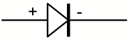
Remember that the direction
of current flow is the opposite of the direction of electron flow. You can view the diode symbol as an
ARROW that points in the direction of current flow.
What do diodes look like and how can you tell which
end is which?
Diodes are often marked with
stripe on one end. The stripe is
on the “–” end, like this:
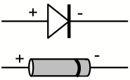
The end with the stripe is
called the CATHODE (K) end and the end without the stripe is called the ANODE
(A) end.
How can I remember which way diodes conduct?
Look at the dark vertical
line in the circuit diagram. Look
at the stripe on the actual part.
These look more like a “–” than a “+”.
In order for the diode to
conduct current, the end with the stripe must be closer to the “ –” end
of the battery and the other end must be closer to the “+” end of the battery.
What is an LED?
LED stands for LIGHT EMITTING
DIODE. An LED functions like a
diode: current will flow through it in only one direction, so an LED must be
hooked up correctly to work.
Furthermore, when current is
flowing through it, it will glow, like a light bulb. LEDs are very efficient, which means they convert almost all
of their power into light. They
run very cool since they produce no waste heat.
A diode is, in theory, a
perfect conductor (in one direction) with zero resistance. Since an LED converts electrical power
into light, it cannot be a perfect conductor. Like any light bulb, there will be some resistance and a
voltage drop across the diode.
However, LEDs often conduct
so well (i.e., have so little resistance) that it is necessary to place a
resistor in series with the LED, to keep it from burning up.
What is DIRECT CURRENT (DC)?
A circuit in which the
electricity flows smoothly and doesn’t change is a DC circuit. Typical examples include any circuit
powered by a battery or a DC power supply. Once it is turned on, the flow of electricity is
constant. You can measure the amps
through the circuit and it the value will be unchanging. You can also measure the voltage at
each point in the circuit and it will be unchanging.
What is ALTERNATING CURRENT (AC)?
In general, any circuit in
which the current and voltage levels are changing is an AC circuit. This includes pretty much every
electronic circuit.
However, the term AC usually
applies to the power we get from household outlets.
The voltage provided by a
battery is constant, for example at 1.5 volts. The current flow is determined by whatever is connected to
the battery. In particular, the
resistance of the circuit matters.
If the battery is unconnected there is infinite resistance and therefore
zero current.
In the case of AC power from
the outlet, the voltage is rising and falling very regularly. Generally one wire (the white wire) is
called the “neutral wire” and has a voltage level of zero volts. The other wire (the black wire) is called
the “hot wire” and has a voltage that swings regularly between +120V and -120V.
This means that if you plug
something in, such as a light bulb with a fixed resistance, the current flow
will change directions. When the
hot wire is at +120V the current will flow in one direction; when the hot wire
drops to zero the current will stop flowing. Then, when the hot wire falls to -120V, the current will
flow in the other direction.
So in a light bulb, the
electrons will flow first one way, then the other way. It is a little like sound waves. When sound waves go through the air,
the molecules move back and forth.
However, the molecules stay close to the same position. Even though they are waving back and
forth, there is no overall movement (unless the wind is also blowing).
With AC power, it is the
same. The electrons first go one
way, then they come back in the other direction.
What is a RECTIFIER?
A RECTIFIER is a small
circuit that converts AC power into DC.
If you have an AC power source, you can use a rectifier to turn it into
DC, so you can power something that requires a DC power source.
A rectifier has two input
wires and two output wires. The
inputs are for the AC power coming in, and it doesn’t matter which wire is
which. The outputs are DC and are
marked “+” (or RED) and
“–” (or BLACK).
Rectifiers are sometimes
called “bridge rectifiers.”
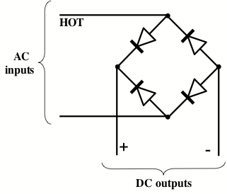
How does a rectifier work?
Here is the circuit diagram
for a rectifier:
To see how this circuit
works, first imagine looking at the circuit at a moment in time when the hot
wire of the AC input is positive, say at +120V. The diodes will allow the current to flow only one way, as
shown in the next diagram. The two
diodes shown in gray are blocking current flow, because they are pointed
against the current flow.
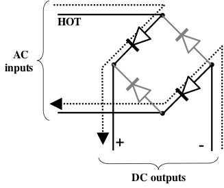
Next imagine looking at the
circuit at a moment when the hot wire of the AC input is negative, say at
-120V. Now the diodes will only
allow the current to flow as shown in the next diagram.
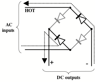
So regardless of whether the
hot line of the AC input is positive or negative, the + output of the DC output
wires will always be positive.
[In these diagrams, the arrow
shows the flow of current. Recall,
that this is actually the opposite of the direction the electrons are moving.]
How can you measure the power output of a generator?
First, you need to get it
turning. Second, the generator
must provide power to something, such as a light bulb. Third, you need to measure both volts
and amps at the same moment.
Fourth, you can use the power equations to compute the watts of power
being produced.
Here (again) are the important
equations:
Amps = Volts / Ohms
Watts
= Amps ´
Volts
Watt-Hours
= Watts ´
Hours
Watt-Hours
= (Amps ´
Volts) ´
Hours
What are OPEN VOLTS?
You can measure the voltage
produced by a battery or a generator in two ways. First, you can measure the voltage when the battery or
generator is powering some device, such as a bulb. Second, you can measure the OPEN VOLTAGE of the battery or
generator, when it is not connected to anything.
To measure the open voltage
of a power supply, simply connect the multimeter probes to the battery or
generator and take a reading.
Since the outputs of the battery or generator are not connected to
anything else that might draw power, this is called the open voltage.
What is a LOAD?
When a battery or generator
is powering something (such as a light bulb), it is loaded. The light bulb (or power tool or
resistor or whatever) is called the LOAD.
Why measure open voltage?
Because a power supply (like
a battery or generator) may supply a different voltage when under load. It is fairly easy to produce high
voltage. As we learned above,
voltage without any current means there is no power. So an unconnected power supply has a current flow of
zero. No matter what the open
voltage is, the power being delivered will be zero.
It is easier to supply zero
power than to supply real power.
When the power supply is loaded, its voltage may drop. For example, if you ask it to supply a
large current, this would mean a large amount of power. Perhaps it cannot supply this much power,
so the power supply will compensate by lowering its output voltage.
For example, a 9V battery
might have an open voltage of 9.2 volts when it is new. If you connect the battery to a light
bulb, and measure the voltage across the battery terminals, you might see a
voltage under load of 8.8 volts.
Then, after disconnecting the bulb, the open voltage might return to
9.2V.
What is the procedure for measuring voltage?
Before you can use your
multimeter, you need to know whether you are measuring DC or AC.
On some multimeters, you need
to plug the probes into different holes, depending on whether you are measuring
AC or DC.
How do you measure DC voltage?
If you are measuring, say, a
battery then you are looking at DC.
Turn the dial on your multimeter to DCV (i.e., DC Volts).
Most multimeters have several
choices and you must select a range.
Your choices might be something like:
200
20
2
200 mV (200
millivolts = 0.200 volts)
20 mV
2 mV
You want to select a number
that is just higher than the voltage you are measuring. If you are not sure what voltage you
have (And why else would you be trying to measure it?) start with the highest
range and work down until you get a reading.
AFTER selecting a DCV range,
connect the probes. You should connect
the red probe to the positive, higher voltage and the black probe to
ground. The multimeter will show a
positive number if the voltage of the red probe is higher than the block probe.
If you get the probes
reversed, a digital multimeter will show a negative number. If your multimeter is not digital, then
it will have a moving needle display.
If the needle slams into the left wall, then reverse your probes and try
again.
How do you measure AC voltage?
You’ll need to select ACV (AC
Volts) on your multimeter. Just
like measuring DC, you’ll need to select a range. If you are unsure, start with the highest range and work
down.
After selecting the highest
range, connect your probes to the circuit. For example, you might push your probes directly into a
household wall outlet.
It doesn’t matter which probe
you connect to which side.
Then select a lower range
until you get a useful reading.
(When measuring voltage
(either AC or DC) you probably do not want to connect the multimeter in series
with any circuit elements. In
other words, don’t break the circuit and insert the multimeter into the
circuit. Instead, just touch the
probes to whatever points you are interested in.)
How can you measure resistance?
You can use a multimeter to
measure the resistance of a component, such as a lamp or resistor.
First, disconnect the
component you want to measure from power and remove it from the circuit. You should test the resistance of a
single thing and there should be no power provided.
Your multimeter has a battery
in it. A multimeter measures
resistance by passing a small electrical current through the device you are
testing. It uses a very small
voltage and will not hurt even the most delicate components.
First, connect your
multimeter probes to the device.
It doesn’t matter which way you connect the probes. (Exception: if you are testing a diode,
direction matters, since the diode has low resistance one way and high
resistance in the other direction.)
On some multimeters you may
need to select a range, so flip the dial around until you get a useful reading.
How do you measure the resistance of a coil?
Coils have a property called
INDUCTANCE, which is beyond the scope of this paper. A coil will resist flow for a while, and it may look like
the resistance is changing.
Another way to say this is that current flow takes a long time to either
start or stop.
To measure the resistance of
a coil, leave the probe attached as long as the reading is changing. Once the reading is stable, then you can
write it down.
How can you get more power from a generator?
Turn it faster!
Of course this is hard work:
you are putting mechanical power in by turning the generator. For example, in a windmill, wind
provides power to turn the generator.
The generator turns wind power into electrical power. The faster the wind blows, the more
mechanical power is transferred to the generator. And this mean that more electrical power will be produced by
the generator.
How efficient is a generator?
It depends on the design and
quality of the generator. Not all
the mechanical power that goes into a generator is converted into electrical
power. Some power will be lost as
heat. The generator will convert
some wind power into waste heat.
In large generators, you
might be able to feel the bearings getting hot and you may also feel the coils
getting warm. Generators and
motors often fail by overheating.
The coils can get so hot the insulation melts and the coil wires short
out.
How do you calculate the power output of a
generator?
To determine the output of a
generator running under load, you need to measure these things:
(1) The RPMs (the revolutions per minute),
(2) The actual voltage observed.
You also need to know these
things about your generator:
(3) The RPMs per open volt,
(4) The resistance of the stator coils.
You can measure the
resistance of the stator coil with a multimeter. The resistance of the stator coil will be measured in Ohms.
You can measure the actual
voltage observed by running the generator under load and measuring the
voltage. Use your voltmeter by
placing the probes in parallel with the load. In other words, leave the load connected and touch the
probes across the generator output wires.
Measuring the revolutions per
minute (the RPMs) will require some test device or some other trick, such as
driving the generator with a motor that produces a known RPM.
Finally, you’ll need to know
the RPMs per open volt produced by your generator. You can determine this by turning your generator at a known
RPM and measuring the open voltage.
(The open voltage is the voltage across the generator with no load
connected.) Then use this formula:
RPMs-per-open-volt = measured-RPMs /
measured-open-volts
Example #1: Turn the generator at 1000 RPMs and
measure the open voltage. Let’s
suppose it turns out to be 23.4 volts.
Then compute…
RPMs-per-open-volt = 1000 / 23.4 = 42.7 RPM/volt
This tells you that if you
turn your generator at 42.7 RPMs you should see an open voltage of 1.0
Volts. If you turn it at 427 RPMs,
you should see 10.0 volts, and so on.
You should see a direct linear relationship between open volts and RPMs.
Example #2: Turn the same generator real fast and
measure the RPMs. Let’s say you
measure 567 RPMs. Then measure the
open voltage. Let’s say you get
13.28 volts. Then compute…
RPMs-per-open-volt = 567 / 13.28 = 42.7 RPM/volt
This is to be expected if
this is the same generator, since it matches the RPMs-per-volt from example #1.
Okay, now we are ready to
measure the generator under load.
So hook up the generator to the load and measure both the RPM-under-load
and the voltage-under-load. Now we
know these values:
RPM-under-load
Voltage-under-load
RPM-per-open-volt
Coil-ohms
Then use this formula:
Amps = ((RPM-under-load / RPM-per-open-volt )
– voltage-under-load ) / Coil-ohms
To get power, recall that the
formula is:
Watts = Amps ´ Volts
(Here, by “volts”, we mean
the volts-under-load.)
Example #3: Assume you hook the same generator up
to a light bulb and turn the generator at a constant speed, causing the light
to glow. Assume that you measure
the RPMs under this load to be 1050 and you measure the voltage across the bulb
to be 35.5V.
Also assume that you have
previously measured the resistance of the coils in the generator and have found
it to be 1.5W.
So, you have these values:
RPM-under-load =
1050 RPM
Voltage-under-load =
15.5
RPM-per-open-volt =
42.7
Coil-ohms = 1.5W
Now, using the formula, find
the amps:
Amps = ((RPM-under-load / RPM-per-open-volt )
– voltage-under-load ) / Coil-ohms
Amps = ((1050 / 42.7) – 15.5) / 1.5
Amps = ((24.59) – 15.5) / 1.5
Amps = (9.09) / 1.5
Amps = (9.15) / 1.5
Amps = 6.06
Next, you can compute the
power output from the generator:
Watts = Amps ´ Volts
Watts = 6.06 A ´ 15.5 V
Watts = 93.93
If you want a given amount of power, how fast do you
have to turn the generator?
Let’s say you want your
generator to deliver 10 amps at 20 volts.
(This would be 200 watts of power output.)
To compute how fast to turn
the generator, we need these numbers.
Desired-Voltage
Desired-Amps
RPM-per-open-volt
Coil-ohms
In this example, we have
these actual values:
Desired-Voltage = 20
Desired-Amps = 10
RPM-per-open-volt =
42.7
Coil-ohms = 1.5
Now use this formula:
RPM =
(Desired-voltage + (Desired-amps * Coil-ohms)) * RPM-per-open-volt
Plugging in our values, we
can compute…
RPM = (20 + (10 *
1.5)) * 42.7
RPM = (20 + (15)) *
42.7
RPM = (35) * 42.7
RPM = 1495
If we attach a load with 2
Ohms of resistance to our generator and turn it at 1495 RPM, we should see 20
volts and 10 amps. That is 200
watts of power being delivered.
[Note: The formulas for
generator power computation came from www.windstuffnow.com/main/generator.htm.]