Overview of Wiring for the Salinity Sensor
Other pages describing fish tank wiring.
Return to the main page for the fish tank wiring.
Schematic
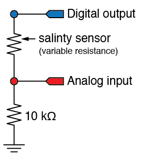
The following schematic shows the circuit for supplying power to the salinity sensor and reading of the sensor output.
The power to the circuit comes from a digital output line. Do not connect the voltage divider to a constant 5V source because a layer of ions will build up around the sensor probes. The ion layer will cause an error in the resistance reading.
Connecting the sensor
The salinity sensor acts like a variable resistor. As indicated in the schematic, the salinity sensor is the upper (higher voltage) resistor in a voltage divider.
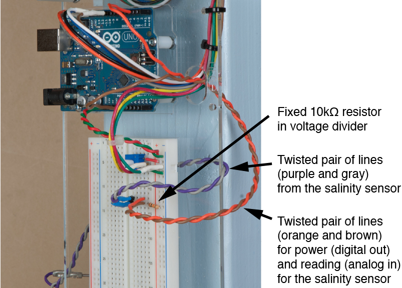
The two stainless steel pins in the sensor body are connected to the breadboard with a pair of wires. In the photograph below, the lead wires on the salinity sensor are purple and gray. The polarity of the wires does not matter.
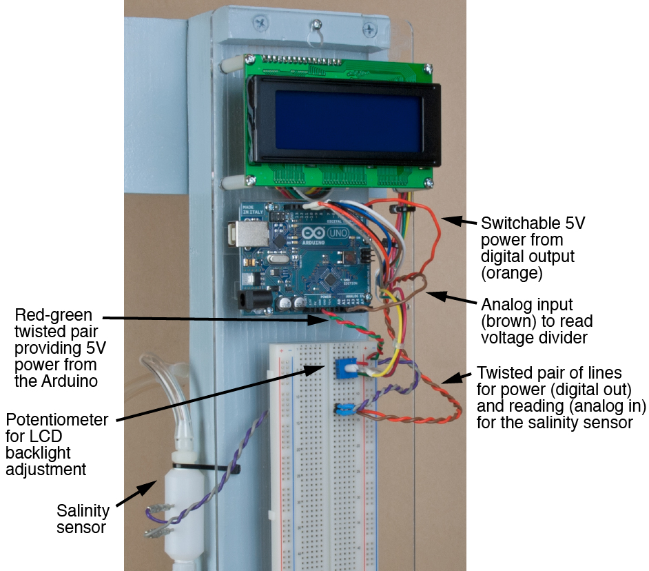
Power to the salinity sensor is supplied by a wire connected to a digital output pin on the Arduino. In the photograph below, the power line (orange) and the analog reading line (brown) are twisted together.
The fixed 10kΩ resistor is on the lower leg of the voltage divider. The fixed resistor ties one side of the salinity sensor to ground. The other side of the salinity sensor is connected to the digital output pin that supplies power to the voltage divider.