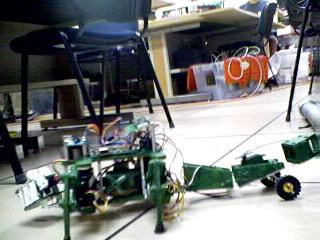
For my project at the PSU robotics lab, I decided to create a robotic alligator that could be used for the robotic theater. Currently I am working on programming it, but the construction is complete. I am in my 6th and final week here, and am hoping to finish the project.
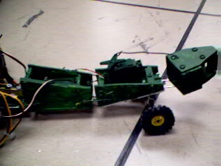
To start out with, I found an assembled quadrapod in the lab that was missing one leg. I noticed that between the top and bottom platforms of the quadrapod were connected by rods, and there was space in the middle, as well as the front and back, to add on stuff. First, I began work on the tail. The tail is the most unstable part of my robot unfortunately, it tends to wobble back and forth.

I created the tail by using PVC boards. I didn't care about the color, since everything would be painted, so some of the boards I cut out were yellow and 1/4" thick, while others were white and 1/8" thick. To cut the boards I used the scroll saw. There are 3 tail segments. The first two have a tapering shape, they get smaller as you look farther down. The boards that taper make up the sides of the segments, underneath is a rectangular-shaped piece for some support on each segment. The last tail segment tapers off, but the pieces that taper are the top and bottom of the segment. Each segment has 4 rods (secured by a screw on each side) connecting the two tapering pieces.
On the first segment of tail I glued a servo (with a glue gun), so the rotation part points outwards to the right (if one is looking at the robot from the back). I glued the servo on the second segment in a way that the rotation part points upward. The last tail segment does not have a servo, but I glued some small PVC pieces vertically between the two tapering pieces.
To connect the whole tail to the body, I made a little attachment. I cut out 2 small pieces of PVC board. I glued one under the bottom body piece in the back if the robot so that it protruded. I glued the other piece on top of that. Then I cut out 2 equal size smaller rectangular pieces and glued them vertically on to the piece sticking out from the body. I took 2 rods and hooked them onto each side of the first segment, and the other ends of them to the 2 rectangular pieces. The second segment was secured in the same way. The third segment has two rods both attached to the bottom of it with the other ends attaching to the bottom of the second segment. In the middle of the body, I put on a big servo to move the whole tail up and down. To make the servos move the segments, I attached a rod to each one and the other end of the rod to the segment I wanted it to move. I realized later that glueing pieces would not give nearly enough support, so I drilled some holes in the pieces and body and put in some screws.
Finally, I drilled 2 holes in the bottom of the second tail segment and attached to threaded hooks. I put in a Lego rod with 2 Lego wheels attached to it. This makes it so the tail doesn't drag too much on the ground.
The construction allows the tail 3 degrees of freedom. The whole tail can move up and down, a smaller part of it can also move vertically, and the last segment can rotate right and left.
The next step was to create the head. I glued a regular servo in the middle of the front body with the rotation part pointing up. The head is made of the same PVC boards that were used in the tail. However, I only used the white 1/8" thick board for good reason.
The mouth is composed of two equal sized pieces that looks like a rectangle that tapers a little bit on each side, but the front is a straight line. I glued the eyes on the top of the mouth. They look like a semicircle combined with a rectangle. To make the teeth, I cut out a long rectangular strip of the PVC board and drew up interlocking triangles on it. I cut these out and made the back teeth on each side a right triangle, so the teeth wouldn't be sticking out the back of the jaw. There are 15 teeth in all; 8 on the top and 7 on the bottom. That gave me the construction of the mouth. Then I had to make the mechanics.
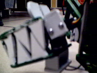
Underneath the bottom jaw I made a little assembly so I could attach a wire from the servo and a wire from the body to allow the mouth to rotate. The assembly is a rectangle, and two pieces glued to it that are rectangles with a triangular piece sliced off the top. I put glue on the top of the two small pieces and connected it to the bottom of the jaw. I drilled 2 holes in the rectangle to allow the wire from the servo and the wire from the body to be attached.
I wanted to make the mouth open and close so I cut out 2 small squares (about half the height of the teeth) and glued them on the top of the bottom jaw. I took a micro servo and screwed another small square vertically onto it and then glued a square horizontally on top of that piece. I glued the edge of the top square to the back of the top jaw and mounted the micro servo onto the two squares on the top of the bottom jaw.
Alright, so that covers the construction of the robot. I painted the whole thing green except the teeth which I left white and the eyes which I painted partly black to look realistic. When painting I was careful around the mechanical parts, so that the robot would be able to move all of its parts freely.
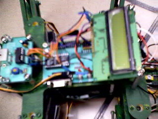
After the construction I put on the boards and the wiring. I followed the diagram in the Next Step manual for the 12 servo walker wiring example, since that gave me room to connect my 13 servos. The boards needed are the Infrared Proximity detector, the Next Step boards, the Serial LCD board, and 2 mini SSC II boards. The diagram shows how to wire everything, and the only change I made from it was that I didn't put on switches, and I hooked up the servos in a different way. On the first SSC board I connected the eight servos for the legs in the following configuration:
0 - Right Front Horizontal
1 - Right Front Vertical
2 - Right Rear Horizontal
3 - Right Rear Vertical
4 - Left Front Horizontal
5 - Left Front Vertical
6 - Left Rear Horizontal
7 - Left Rear Vertical
On the second SSC board, I connected the remaining servos in the following manner:
0 - Head rotation
1 - Jaw movement (up and down)
2 - Complete tail vertical movement
3 - Partial tail vertical movement
4 - Tail segment rotation
It was necessary to make an extender cord for the micro servo so that it could physically reach the SSC board.
To mount the boards I used some creativity and packed them into as tight a space as possible. On the top, I put the IRPD, the next step board, the SSC board with 5 servos connected and the LCD screen. For the IRPD, I had a post under each corner so as to raise it above the jaws' range of motion, so the jaw would not set it off. For the serial LCD screen, I put two posts under each corner (connected by a threaded screw with the top sawed off). It was mounted this way because otherwise, there would not have been space for it. I put the other SSC board on the bottom piece of the alligator body at the back. The boards were all mounted by putting a screw in each corner and onto the body.
Currently I am working on the programming part of the robot and am encountering some difficulties. I downloaded a pre-made quadrapod program that is supposed to enable the robot to walk forward at different speeds and to crouch and stand up. After some alterations, I was able to successfully make the alligator crouch and stand, and it could walk forward but was weighed down by the long tail causing the front end to tilt up a little.
Recently, while working with the robot, I noticed plenty of smoke coming out from the circuits. I thought that one of my servos had short-circuited which turned out to be the case. The problem extended beyond replacing the wires though. The robot had the program loaded onto it, but would not move the servos. I rechecked all of the wire connections and made some changes. Then, I replaced the SSC board (the one with 5 servos connected) as well as the next step board.
This puts me at my present stage. The robot will move the servos now, but I need to load on a new program. When I try to do this, an error message pops up saying 'check power supply' despite my batteries being connected and in fine working order.
In this program at PSU, I learned a fair amount about the mechanics of robotics and how many different functions they performed. The work was very independent which made figuring out things more enjoyable. The downside was that it could be frustrating sometimes. I didn't learn very much at all about practical programming of robots using the language PBasic. I enjoyed learning about LISP, but that didn't apply to our robots. When I was trying to figure out how to work with PBasic, and then my robot short-circuited, that was upsetting. Still, I found this to be an enjoyable experience and it was fun to be working with other kids my age.
I would suggest that for the next year's program, there should be more learning. Maybe a process to introduce kids to robotics and constructing them, and then lectures on practical programming of robots with examples. If people could see the program controlling the robot and making it move, that would implant ideas in their head better than just seeing stuff written on the board.