Assembly of the Female Connector Block
The wiring harness has a male and female end. The gender of electrical and mechanical parts is described on this Wikipedia page. The header pins that are soldered into the circuit board for the LCD panel are plugged into the female end of the wiring harness.
This web page describes how to fabricate the female end of the wiring harness. The entire assembly and test process is divided into the following steps.
Wire harness components
Each team of two students will pick up a set of components shown in the following photograph. The number of crimp pins will be greater than the four in the photograph.
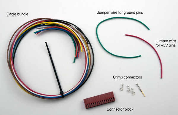
The cable bundle has nine stranded wires, each with a different color of insulation. The wires are 22 AWG and approximately 40 cm (16 inches) long. The bundle is held together with a loosely cinched zip tie. Do not tighten the zip tie until the wiring harness is finished. You may need to adjust the wires so that the ends line up. Furthermore, tightening the zip tie before you finish will make the bundle stiffer, which will make it harder to adjust the orientation of individual wires as they are crimped.
When the wire harness is finished, one end of the cable bundle will only have female crimp connectors, and the other end will only have male crimp connectors. Pay attention so that you do not mix the genders on the ends of the wires as you add crimp connectors. Of course, there is no initial difference between the end of the wires.
The connector block has sixteen sockets for either male or female crimp connectors. We will only use twelve of the sixteen sockets. Only female crimp connectors will be used in the connector block, so we will refer to this as the female connector block.
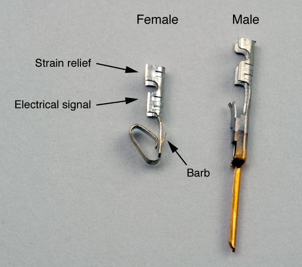
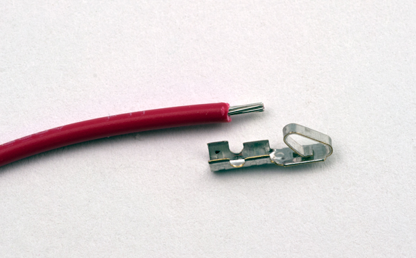
The small metal parts are the crimp connectors that are attached to the ends of the wire with the crimping tool. The following photo is a close-up view of the female and male crimp connectors. Each crimp connector has two sets of tabs: one for connecting to the stranded conductor in the wire, and another for grabbing the insulation as a strain relief. A small metal barb on one side of the connector locks the crimp connector to the connector block when the crimp connector is inserted into the block.
Green and red jumper wire
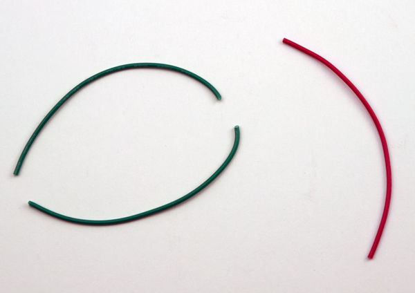
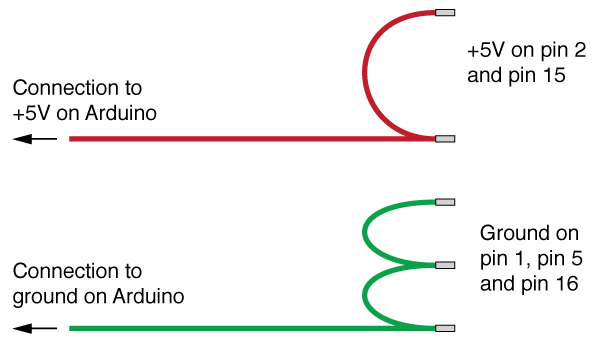
The green jumper wire is used to electrically connect three ground pins on the female end of the connector. The red jumper wire is used to connect two +5V power pins on the female end of the connector.
Gently fold (do not bend) the green jump wire so that it forms a "U" shape, and cut the green wire in half.
The following sketch shows how the red and green jumper wires are connected to the red and green wires in the cable bundle. The long, horizontal red and green wires are the 40 cm wires from the cable bundle. The red jumper cable connects two pins in the female connector block. The two green jumper cables connect three pins in the female connector block.
Strip one end of the short red wire
Make your first crimp with the short red jumper wire. This will allow you to practice with a length of wire that is easy to hold. If something goes wrong, you can cut the end and start again.
Using the crimp connector as a reference, strip one end of the red jumper wire. The bare wire should be a little longer than the tabs closest to the curled end of the crimp connector. Compared to other applications, such as joining two wires, or attaching a wire to a screw terminal, this is a very short length of bare wire.
Get ready to crimp
The crimping operation will take two squeezes of the crimp tool handles. The first squeeze crimps one pair of tabs onto the bare electrical wire and starts the crimp on the strain relief tabs. The second squeeze secures the strain relief tabs. For these two squeezes, the tabs being crimped are in the black side of the crimp tool.
The crimp connectors and wires are small. Holding everything in place takes a steady hand and some patience. It is easy to become frustrated. However, with a little practice, it becomes easier to make the crimp connections. Once you develop your technique, it is possible to make a crimp connection in 15 to 20 seconds, start-to-finish.
Locate the pieces in the crimp tool
Orient the crimp tool so that you are looking at it from the un-labeled side (no AWG indicator marks showing). The crimp tab surrounding the bare end of the wire should be above the black side of the jaws. The crimp tab surrounding the insulated end of the wire should be above the gray side of the jaws.
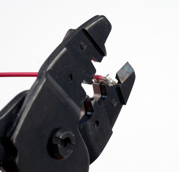
Crimp the electrical connection
Carefully close the jaws of the crimp tool by squeezing the handles. Monitor the orientation of the crimp connector and the alignment of the bare wire to the crimp tab. It is very easy for the wire and crimp tabs become misaligned.
After the first crimp, release the handles of the tool and slide the wire and crimp connector so that the tabs for the strain relief are aligned with the black side of the crimping tool jaw. Squeeze the handle to crimp the strain relief.
The finished crimp connection should look something like the following photo
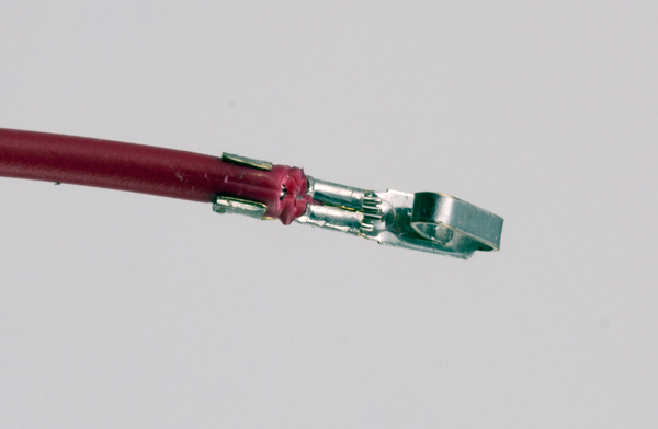
Set aside the red jumper wire with the newly crimped connector.
Prepare the green jumper wire
The next step is to join two wires with a single crimp connector. This is needed to connect the short jumpers to each other, and to the longer wires in the bundle.
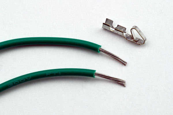
Strip one end of each of the two short green jumper wires. This strip should expose a longer section of bare wire — longer than the stripped section for the red jumper wire. As shown in the following sequence of photographs, the bare wire should be long enough to completely fill the space between both pairs of tabs on the crimp connector.
After stripping the two lengths of wire, twist them together...
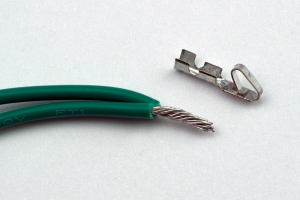
and then lay them in the space between the pairs of tabs..
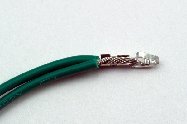
Crimp both of the tabs to the bare wire.
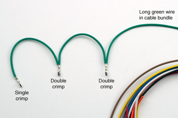
Finish the ground wire with two jumpers
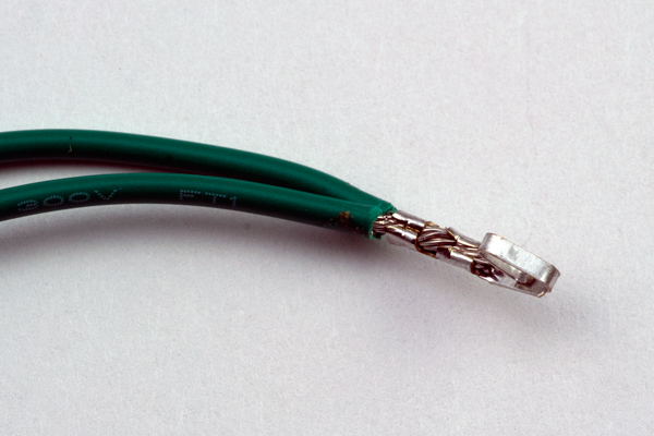
Finish the female end of the ground cable by creating another double-crimp connection to the long green wire in the cable bundle, and a single-crimp connection on the short jumper with the free end. The final configuration should look something like the following picture. Remember that the double-crimp connections require longer strips of bare wire than the single crimp connection.
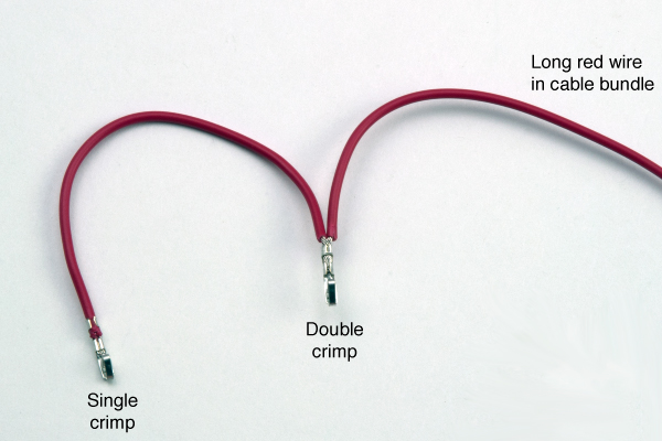
Finish the power wire with one jumper
Use a double-crimp joint to connect the free end of the red jumper wire to the long red wire from the cable bundle. The result should look like the following photo.
Add crimp connectors to ends of remaining wires
For all the remaining wires on the female end of the wire bundle, repeat the steps for the single connection
- Strip approximately 1mm of insulation from the end of the wire
- Locate the wire in the crimp connector so that one set of tabs are aligned with the bare wire and the other set of tabs are aligned with the insulation.
- Crimp the tabs over the bare wire
- Reposition the wire so that the strain relief tabs are over the black part of the jaws. Crimp the tabs over the strain relief.
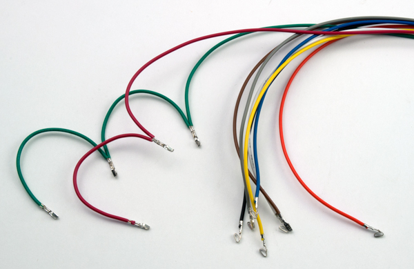
The following pictures show the wires with the finished crimp connectors.
Insert crimp connectors into the cable housing
The last step is to insert the newly formed crimp connectors into the cable housing. This step is easy, but do not rush it because the order and orientation of the pins in the connector block matter.
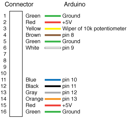
The following schematic is the wiring diagram for the connector block. The pin positions on the connector block are listed on the left side. Note that the pin number on the connector block is independent of the pin numbers on the Arduino. Details of the Arduino connection are provided on another web page.
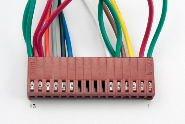
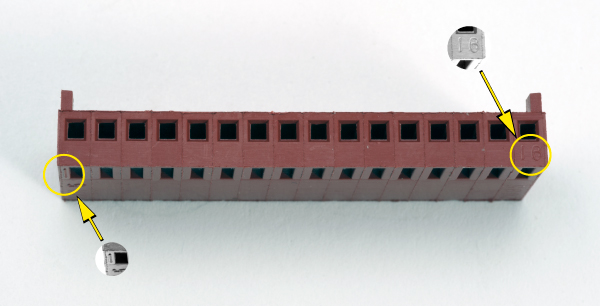
The pin number is indicated in two places on the connector block. The following photograph shows the number 1 embossed on the face of the block near the barb socket, which is on the left end of the photograph. The number 16 is embossed on the face of the connector that will mate with the LCD panel.
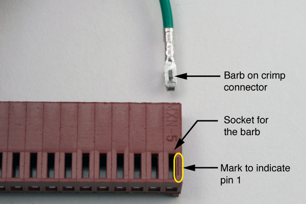
The next photograph shows the correct orientation of a pin before it is inserted into the connector block. The barb on the crimp connector is aligned so that it catches in the barb socket on the connector block.
Finished connector block
The finished connector block should look something like the following photograph. The location of pin 16 and pin 1 are indicated. The four empty sockets in the middle of the connector are not used.